
Lens type antenna housing

A radome and lens technology, applied in the field of radomes, can solve the problems of inability to form an omnidirectional antenna array, increase the beam width, and decrease the gain, and achieve the effects of simple structure, increased gain, and easy processing.

Inactive Publication Date: 2011-11-23
ZHEJIANG UNIV
View PDF4 Cites 7 Cited by
  • Summary
  • Abstract
  • Description
  • Claims
  • Application Information

AI Technical Summary

Problems solved by technology

[0005] Therefore, the antenna array replaces a single antenna and becomes a solution with high directivity and high gain. However, most antenna arrays have good directivity and high gain at high elevation angles, and the beam width will become larger at low elevation angles. will become smaller and cannot form an omni-directional antenna array

Method used


Image

  • Lens type antenna housing
  • Lens type antenna housing
  • Lens type antenna housing

Examples


Embodiment Construction

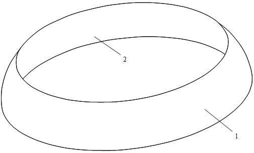
[0015] Such as figure 1 , 2 As shown, the lens radome is a hollow ellipsoid table, the outer surface 1 of the lens radome is ellipsoid, the inner surface 2 of the lens radome is spherical, the longitudinal section of the lens radome is half crescent, and the lens The wall thickness of the type radome gradually decreases from bottom to top. The lens radome of this structure can be regarded as a crescent lens in each longitudinal section.

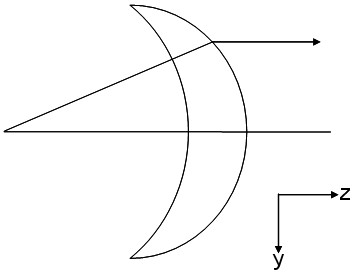
[0016] Such as image 3 As shown, the inner surface of the crescent lens is circular, and the outer surface is elliptical. It belongs to a single refraction surface lens, and its refraction occurs on the outer surface, and the inner surface is normal incidence. Its geometric shape is determined by the following formula (in Cartesian coordinate system):

[0017] Outer Surface: Oval

[0018] Inner surface: round

[0019] in

[0020]

[0021]

[0022] D is the diameter of the crescent lens, and f is the focal length of the cre...


PUM


Abstract

The invention discloses a lens type antenna housing which is a hollow elliptical table and is provided with an outer elliptical surface, an inner spherical surface, a half-crescent-shaped longitudinal section and a wall thickness reduced gradually from bottom to top. One or three protection layers are arranged on the inner surface of the lens type antenna housing. The three protection layers include a first protection layer, a second protection layer and a third protection layer from outside to inside. The first protection layer and the third protection layer are made of low-dielectric constant materials, and the second protection layer is made of high-dielectric constant material. The lens type antenna housing has the characteristics of simple structure, single materials, easiness in processing, and the like, and can be used in an antenna array requiring high directivity and high gain, especially in beam communication or anti-interference systems such as satellite communication, radars and the like in an omnidirectional antenna array.

Description

technical field [0001] The invention relates to a radome, in particular to a lens type radome. Background technique [0002] With the rapid development of microwave technology, the core supporting role of communication in military and civilian applications has become more and more obvious, and now the antenna has become the most important link restricting the development of communication. Regardless of whether it is for military or civilian use, information is an important component, and maintaining smooth communication anytime and anywhere has become a necessary requirement. [0003] In various mobile communication and electronic countermeasure systems, due to the diffusion of electromagnetic waves in free space and the loss during propagation, the actual useful energy is very small, which requires that the transmitting and receiving antennas can have Higher gain to ensure a sufficiently large communication signal. The level of antenna gain is a very important index to ev...

Claims


Application Information

Patent Timeline
Patent Type & Authority Applications(China)
IPC IPC(8): H01Q1/42H01Q15/02H01Q15/08
Inventor 吴锡东周建华杨楠王中元楚恒林杨龙周金芳
Owner ZHEJIANG UNIV
Learn More