

A hardware-in-the-loop real-time simulation system and a method for realizing rapid prototype control
A real-time simulation and semi-physical technology, applied in the field of data simulation, can solve problems such as complex wiring, increased system usage costs, and high cost of data acquisition cards, achieving low cost and great practicability
- Summary
- Abstract
- Description
- Claims
- Application Information
AI Technical Summary
Problems solved by technology
Method used
Image

Examples
Embodiment Construction
[0045] In order to make the above-mentioned features and advantages of the present invention clearer and easier to understand, the specific implementation manners of the present invention will be explained in more detail below in conjunction with the accompanying drawings.
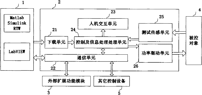
[0046] Such as figure 2 As shown, the figure is a structural implementation diagram for realizing rapid prototype control in the present invention, including a host machine 1, a main control machine 2, an external expansion module 3, and a controlled object 4.
[0047] The host computer 1 is any computer with x86 structure, and its structure can be a notebook computer, an industrial computer, a PC104 host computer, etc. according to different needs.
[0048] The host machine runs Windows operating system and related compilation software, as well as simulation result observation and control software. The function of compiling software is divided into three levels, the first level is to convert the graphic...
PUM
 Abstract
Description
Claims
Application Information