Selective laser melting rapid prototyping equipment for direct manufacturing of large parts

A technology for selective laser melting and molding equipment, which is applied in the direction of improving process efficiency and energy efficiency, and can solve the problems of inability to process large-sized parts, decrease in processing efficiency, and low precision, so as to ensure long-term stable operation and reduce manufacturing costs. Cost, the effect of improving molding efficiency

Active Publication Date: 2011-12-07
TECH LASER TECH SHANGHAI CO LTD
View PDF7 Cites 143 Cited by
  • Summary
  • Abstract
  • Description
  • Claims
  • Application Information

AI Technical Summary

Problems solved by technology

If a mechanical structure is used to move the optical system, the processing efficiency will be greatly reduced
[0009] (2) The shape complexity of the machinable parts is inconsistent with the size of the parts
The laser cladding direct manufacturing parts technology based on automatic powder feeding can only directly form large-sized, simple-shaped blanks; although the selective laser melting rapid prototyping technology is not affected by the complexity of the parts, the size of the parts is far from less than the former
[0010] (3) The dimensional accuracy of the machinable parts is inconsistent with the processing efficiency
[0011] In short, the existing laser rapid and direct manufacturing of parts cannot achieve the organic unity of large-scale, high-efficiency, high-precision and high-complexity manufacturing
[0012] In addition, no matter from the patents at home and abroad or from the existing industrial application equipment abroad, the existing equipment is either not high in precision, poor in performance, low in forming efficiency, or unable to process large-sized parts, etc.

Method used


Image

  • Selective laser melting rapid prototyping equipment for direct manufacturing of large parts
  • Selective laser melting rapid prototyping equipment for direct manufacturing of large parts
  • Selective laser melting rapid prototyping equipment for direct manufacturing of large parts

Examples


Embodiment Construction

[0048] The present invention is described in more detail below by means of examples, but the following examples are only illustrative, and the protection scope of the present invention is not limited by these examples.

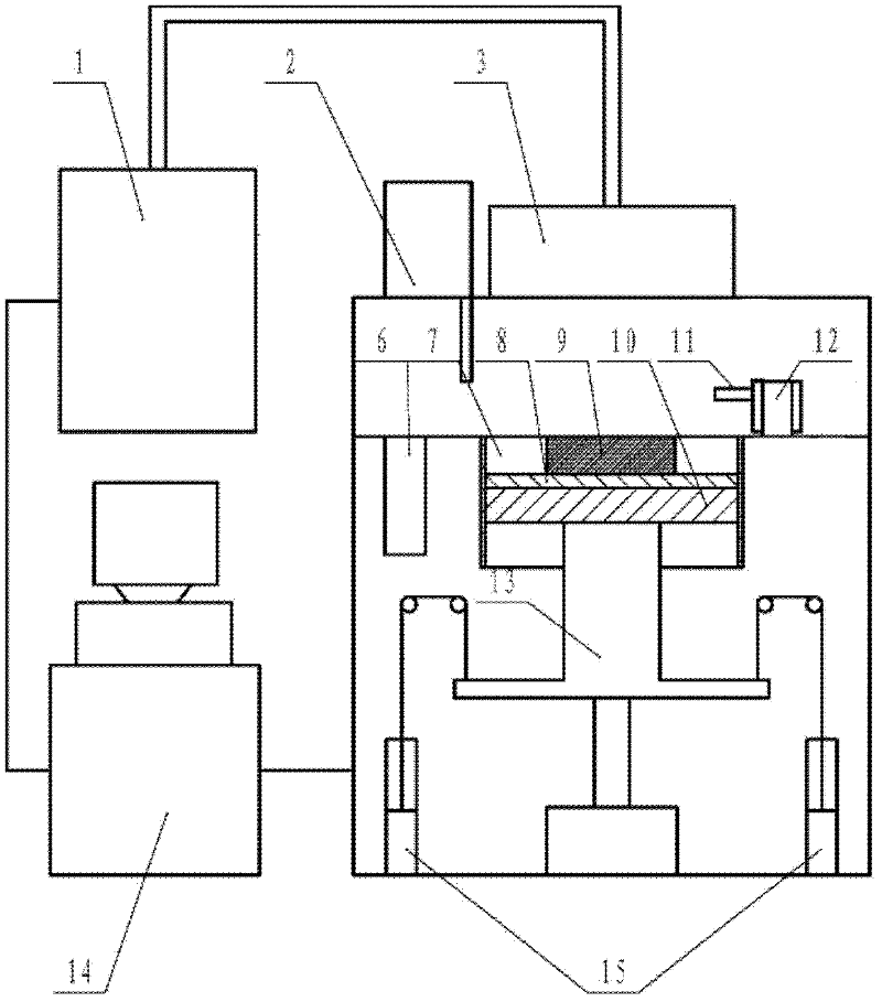
[0049] Such as figure 1 As shown, a specific embodiment of the selective laser melting rapid prototyping equipment involved in the present invention includes a laser group 1, an optical system 3, a substrate 8, a substrate lifting mechanism 13, a molding cylinder 7, a molding cylinder weight balance mechanism 15, a recycling Cylinder 6, quantitative powder feeding mechanism 2, powder spreading device 12 and control system 14.

[0050] The surface of forming cylinder 7 and the surface of recovery cylinder 6 are the same plane, that is, the processing plane, and the powder spreading device 12 can move left and right on the processing plane. The optical system 3 is located directly above the molding cylinder 7 , and the quantitative powder feeding mechanism 2 is...


PUM


Abstract

The invention discloses a selective laser melting rapid forming device for directly manufacturing large-size compact parts, which mainly comprises a laser array, an optical system array, a forming cylinder, a forming cylinder vertical sectional heating thermal-insulation structure, a forming cylinder weight balancing system, a substrate leveling device, a double-recovering cylinder, a double powder storing box, a double quantitative powder sending and discharging device, a powder paving device, a protective atmosphere cover, a gas purifying system and a control system, wherein an adopted optical system is composed of a plurality of optical system units and a mechanical moving platform, and the coverage area of the optical system can be randomly expanded or reduced. The size of the parts manufactured by using the selective laser melting rapid forming device provided by the invention is more than the size of the parts manufactured by using the existing national and foreign selective laser melting processes. The forming efficiency is multiplied while the forming precision, the parts complexity and the mechanical property are not changed.

Description

technical field [0001] The invention belongs to the field of laser rapid manufacturing, and specifically relates to a selective laser melting rapid prototyping equipment for large-sized, high-precision and complex-structured parts. The parts can be metal, non-metal or composite materials of metal and non-metal. Background technique [0002] At present, there are two ways of direct and rapid laser manufacturing of parts: one is the laser cladding direct manufacturing technology (Direct Laser Fabrication-DLF) based on synchronous powder feeding or wire feeding process, which fixes the laser processing head on the machine tool and can move in the Z direction. On the movement axis of the machine, the metal powder or metal wire fed in synchronously is melted by the focused laser beam, and the single-layer manufacturing of parts is realized by controlling the movement of the worktable on the XY plane according to the planned trajectory. After completing the manufacture of one laye...

Claims


Application Information

Patent Timeline
Patent Type & Authority Applications(China)
IPC IPC(8): B22F3/105B29C67/04
CPCY02P10/25
Inventor 曾晓雁王泽敏关凯胡乾午李祥友高明
Owner TECH LASER TECH SHANGHAI CO LTD
Why Eureka
Try Eureka