A magnetron resistance spot welding method and device

A technology of magnetron resistance and power conversion device, which is applied in resistance welding equipment, welding power source, welding equipment and other directions to achieve the effect of saving cost, wide application range and improving connection strength

Active Publication Date: 2011-12-07
SHANGHAI JIAO TONG UNIV
View PDF7 Cites 17 Cited by
  • Summary
  • Abstract
  • Description
  • Claims
  • Application Information

AI Technical Summary

Problems solved by technology

However, the patent does not address how to control the magnetic field and weld

Method used


Image

  • A magnetron resistance spot welding method and device
  • A magnetron resistance spot welding method and device
  • A magnetron resistance spot welding method and device

Examples


Example Embodiment

[0039] Example

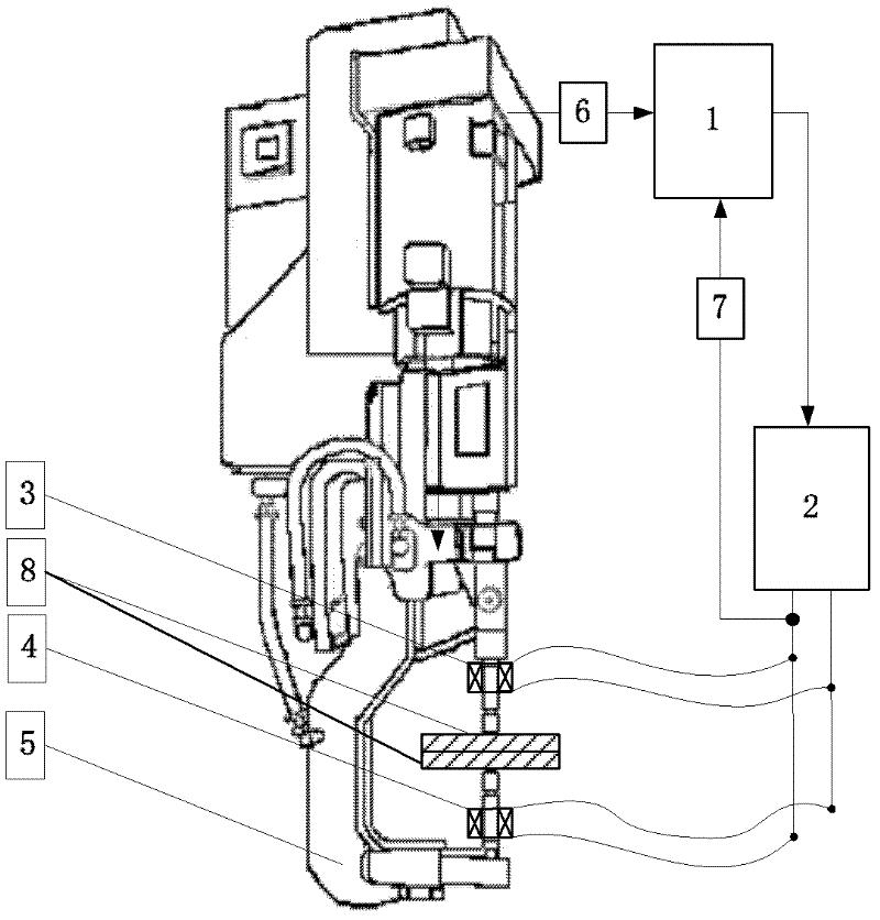
[0040] The hardware structure of the present invention includes a synchronization system 1 , a power conversion device 2 , an upper excitation coil 3 , a lower excitation coil 4 , a resistance spot welding torch 5 , a first current sensor 6 , a second current sensor 7 , and a workpiece 8 to be welded. Wherein: the input end of the synchronization system 1 is connected to the resistance spot welding torch 5 through the first current sensor 6, and the input end of the synchronization system 1 is respectively connected to the upper excitation coil 3 and the lower excitation coil 4 through the second current sensor 7; the synchronization system 1 The output end is connected with the input end of the power conversion device 2 to transmit the electromagnetic stirring synchronization control signal and the excitation coil protection signal. The upper excitation coil 3 and the lower excitation coil 4 are respectively fixed at the upper and lower electrodes of the resi...


PUM


Abstract

The invention relates to a magnetic control resistance spot-welding method and a magnetic control resistance spot-welding device. The method comprises the following steps that: 1) when a magnetic control system is in a startup state or a reset state, a synchronization system continuously detects switching-on and switching-off as well as the intensity of welding current of a resistance spot-welding gun through a first current sensor and judges whether the resistance spot-welding gun has current or not; if the resistance spot-welding gun has the current, a step 3) is executed; and otherwise, a step 2) is executed; 2) the synchronization system sends a switching-off digital signal 00 to a power conversion device to keep the switching-off state of the power conversion device, and returns to the step 1), and the like. The device comprises the synchronization system, the power conversion device, an upper excitation winding, a lower excitation winding, the resistance spot-welding gun, the first current sensor and a second current sensor. Compared with the prior art, the method and the device have the advantages that: an external magnetic field and the welding current can be controlled coordinately, the comprehensive mechanical performance of a resistance spot-welding head can be improved effectively, the applicability range is wide, and the like.

Description

technical field [0001] The invention relates to the technical field of magnetron welding, in particular to a magnetron resistance spot welding method and device. Background technique [0002] As early as the 1970s, the former Soviet scholar M.A.Abralov (Automatic Welding, Vol.30, No.5, 52-55, 1977) studied the crystalline structure and Mechanical properties, the results show that the external magnetic field can effectively refine the primary crystal structure of the weld metal and improve the joint strength. However, due to the large difference in the process between resistance spot welding and arc welding, this technology cannot be directly applied to the field of resistance spot welding: [0003] (1) Different from the moving heat source welding of arc welding, resistance spot welding belongs to the fixed position welding process, and its overall welding process includes three stages of preloading, heating and holding pressure. For resistance spot welding of common metal...

Claims


Application Information

Patent Timeline
IPC IPC(8): B23K11/11B23K11/24B23K11/36
Inventor 李永兵林忠钦沈琦来新民陈关龙
Owner SHANGHAI JIAO TONG UNIV
Why Eureka
Try Eureka