Laser Thermal Effect Compensation System

A compensation system and thermal effect technology, applied in the field of optoelectronics, can solve the problems of high cost, change of cavity structure, and difficult tuning, etc., and achieve the effect of low cost, simple tuning and obvious effect

Inactive Publication Date: 2011-12-14
FUJIAN INST OF RES ON THE STRUCTURE OF MATTER CHINESE ACAD OF SCI
View PDF3 Cites 6 Cited by
  • Summary
  • Abstract
  • Description
  • Claims
  • Application Information

AI Technical Summary

Problems solved by technology

[0017] However, these methods can only correct the first-order term of the thermal lens effect, or can only be statically corrected, or the tuning is difficult, or the cost is high, or the cavity structure needs to be changed

Method used


Image

  • Laser Thermal Effect Compensation System
  • Laser Thermal Effect Compensation System
  • Laser Thermal Effect Compensation System

Examples


Embodiment Construction

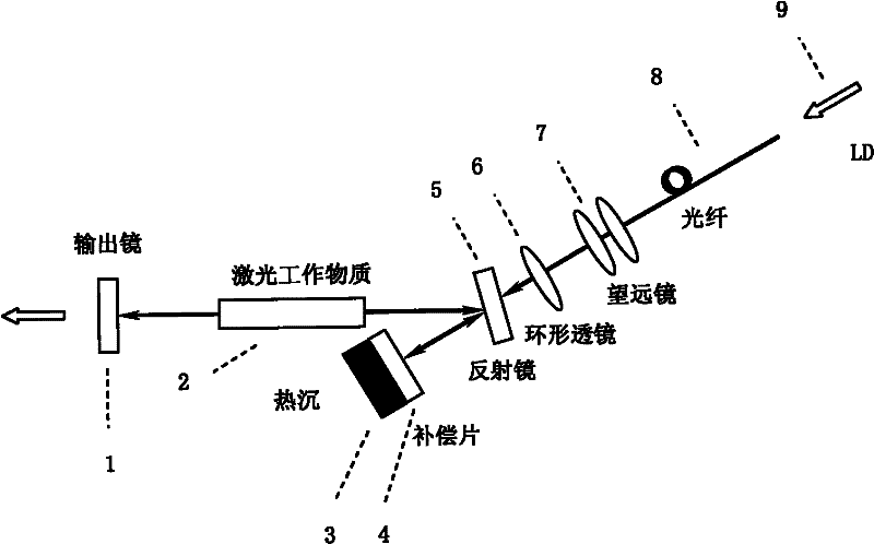
[0030] The following is attached figure 1 with 2 Embodiments of the present invention will be further described.

[0031] figure 1 The middle ring lens (6) converts the transmitted light of the LD (9) through the optical fiber (8) and the telescope (7) into a ring beam; it can be changed by replacing the ring lens with a different focal length or adjusting the distance between it and the telescope or the compensation sheet (4). Relative to the distance, adjust the size of the light spot it hits on the compensation sheet;

[0032] The mirror (5) is coated with a high-reflectance coating (High-reflectance Coating, HR Coating) for the laser beam on one side facing the resonator, and both sides are coated with an anti-reflection coating (Anti-reflectance Coating, AR Coating) for the beam emitted by the LD;

[0033] The compensator material itself is completely transparent to the laser beam, and has a high absorption rate (for example, greater than 90%) for the LD beam; and the ...


PUM


Abstract

The invention provides a novel method for compensating the thermal effect of a solid-state laser. A thermal effect compensation system is added in the laser oscillation cavity, which consists of a heat sink (3), a compensation sheet (4), an annular transmittance lens (6), a telescope (7), an optical fiber (8), and an LD (9) . By adjusting the cooling temperature of the heat sink, the input power of the LD, or the displacement or focal length of the annular transmittance lens, the bulk temperature distribution of the compensation sheet can be finely changed, and the thermal lens effect of the laser working substance (2) can be compensated. By designing different body and surface temperature distributions of the compensation sheet, the invention can be used to compensate thermal lens effects of various orders of different lasers such as rods, slabs, side pumps, and end pumps. It is characterized in that an optical medium that can dynamically adjust its own temperature distribution and a corresponding temperature control system are inserted into the laser resonator cavity to realize fine dynamic compensation for the thermal effect of the laser.

Description

technical field [0001] The invention relates to the field of optoelectronic technology. Background technique [0002] Diode Pumped Solid-State Laser (DPSSL) is a type of laser that uses a laser diode (Laser Diode, LD) or a laser diode array (Laser Diode Array, LDA) instead of a flash lamp as a solid-state laser pumping source . [0003] When the laser working material of DPSSL is subjected to the action of pump light to generate laser light, part of the pump light energy is converted into heat. The main reasons are: a) between the pump band and the upper energy level of the laser, and between the lower energy level of the laser and the ground state The energy difference between them is dissipated into the matrix lattice in the form of heat, causing quantum depletion to generate heat; b) the quantum efficiency of the fluorescence transition process is less than 1, so the quenching process generates heat; c) the absorption heat of the host material. Thus, an "internal heat s...

Claims


Application Information

Patent Timeline
Patent Type & Authority Applications(China)
IPC IPC(8): H01S3/04H01S3/136
Inventor 刘嘉黄见洪戴殊韬郑晖李锦辉史斐翁文葛燕邓晶阮开明林文雄
Owner FUJIAN INST OF RES ON THE STRUCTURE OF MATTER CHINESE ACAD OF SCI
Why Eureka
Try Eureka