Construction method of a bearingless synchronous reluctance motor suspension system

A synchronous reluctance motor and system construction technology, applied in the direction of electronic commutator, etc., can solve problems such as complex algorithm, reduced motor reliability, poor transient regulation performance, etc.

Active Publication Date: 2011-12-14
江苏星科冶金机械制造有限公司
View PDF5 Cites 14 Cited by
  • Summary
  • Abstract
  • Description
  • Claims
  • Application Information

AI Technical Summary

Problems solved by technology

[0003] At present, in the bearingless synchronous reluctance motor suspension system, most of the accurate detection of the radial displacement of the rotor adopts the mechanical eddy current displacement sensor. The defects brought by the displacement sensor are: the displacement sensor increases the manufacturing cost of the motor system, and at the same time leads to the motor. Increased size reduces the reliability of the motor
A national invention patent application (Application No.: 201010017952.6) has been disclosed in the prior art about a displacement sensorless control method for a bearingless synchronous reluctance

Method used


Image

  • Construction method of a bearingless synchronous reluctance motor suspension system
  • Construction method of a bearingless synchronous reluctance motor suspension system
  • Construction method of a bearingless synchronous reluctance motor suspension system

Examples


Example Embodiment

[0073] In order to make the content of the present invention more obvious and understandable, further description will be given below in conjunction with the accompanying drawings and specific embodiments.

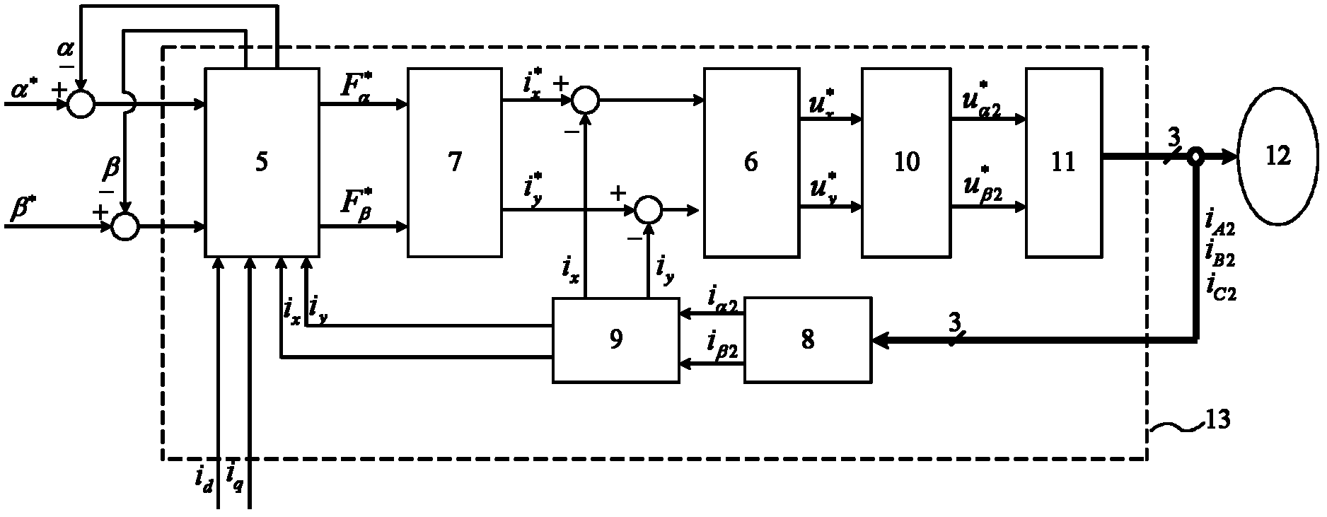
[0074] Construct a suspension system based on rotor displacement observation of bearingless synchronous reluctance motor and internal model decoupling control of suspension winding current. The structure principle of a preferred embodiment of the present invention is as follows image 3 :

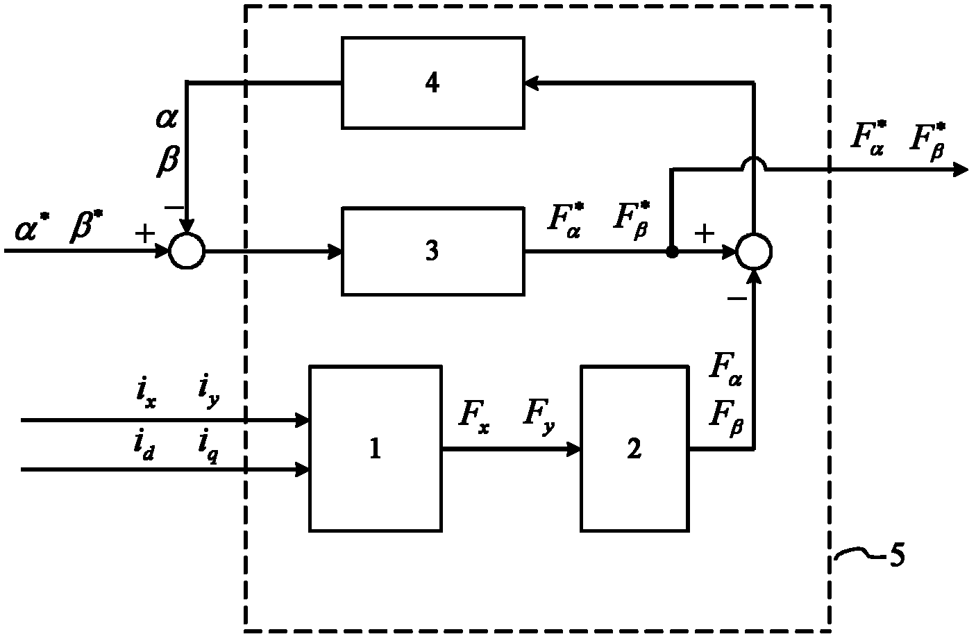
[0075] Build an extended displacement observer 5, combine figure 1 The extended displacement observer is composed of a suspension force observation 1, a PI adaptive rate 4, a PID regulator 3 and a Park inverse transform 2.

[0076] Detect and obtain the three-phase currents of the suspension winding and the torque winding of the motor, and obtain the two-phase currents under the synchronous rotating coordinate after coordinate transformation, which are the equivalent two-phase currents of the ...


PUM


Abstract

The invention discloses a method for constructing a bearing-free synchronous reluctance motor suspension system. During construction of the system, the method comprises the following steps of: constructing an expanded displacement observer; then transmitting three-phase detection current, which is subjected to coordination transformation, of a motor suspension winding and a torque winding into the input end of the expanded displacement observer; synchronously outputting a rotor displacement observed value and a suspension force reference value by the expanded displacement observer as input signals of an expanded suspension force/current modulator; transmitting deviations between two output current component rated values and two-phase detection current subjected to the coordination transformation into two input ends of an inner die controller respectively, and outputting two voltage rated signals as input voltage of a space vector pulse width modulation (SVPWM) inverter; supplying power to the motor suspension winding by the SVPWM inverter so as to generate an expected suspension force, and thus realizing rotor displacement observation for a controlled motor and decoupling control for the inner die of current of the suspension winding. The constructed suspension system has the advantages of high response speed, simple structure, high performance and the like.

Description

technical field [0001] The invention relates to the technical field of AC motor control, in particular to a bearingless synchronous reluctance motor suspension system construction method based on rotor displacement observation and current internal model decoupling control method, which is suitable for bearingless synchronous reluctance motor suspension system under high-speed conditions without displacement sensors. Resistance motor current decoupling control. Background technique [0002] The bearingless synchronous reluctance motor is to superimpose an additional set of windings (suspension windings) on the stator windings (torque windings) of ordinary synchronous reluctance motors to generate a radial magnetic levitation force that supports the constant suspension of the rotor and control two sets of motors. The current of the winding can make the motor generate electromagnetic torque and levitation force at the same time. The special structure determines that the bearin...

Claims


Application Information

Patent Timeline
IPC IPC(8): H02P6/18
Inventor 孙刚张汉年徐开军
Owner 江苏星科冶金机械制造有限公司
Why Eureka
Try Eureka