
Dynamic pressure circulating lubrication roller bit

A technology of circulating lubrication and roller cone bits, which is used in drill bits, drilling equipment, earth-moving drilling, etc., can solve problems such as unsatisfactory lubrication effect, reduced drilling speed, and impact on sealing performance, so as to achieve obvious and reliable flow power and long life of the drill bit. Improved, reliable sealing performance

Inactive Publication Date: 2011-12-21
三原石油钻头厂
View PDF7 Cites 5 Cited by
  • Summary
  • Abstract
  • Description
  • Claims
  • Application Information

AI Technical Summary

Problems solved by technology

Poor lubrication is directly reflected in the premature fatigue of the bearing sliding pair or rolling pair, and the bearing cannot withstand high drilling pressure and high speed, resulting in a significant reduction in drilling speed
The second is that the roller cone bit is poorly lubricated, the temperature in the bearing cavity accumulates, and it cannot be released when the pressure rises, which has a fatal impact on the maintenance of the sealing performance
[0003] In the lubrication system of roller cone bits currently used, the bit grease can only circulate partially in the bearing cavity, and a very small amount of drill bit grease in the bearing cavity is reused, and the lubrication effect is not ideal
Some existing roller cone bits try to use the drill bit grease in the external oil storage hole, but because there is no reasonable circuit for drill bit grease circulation, or the lack of circulation power, the drill bit grease can only fluctuate back and forth within a certain range, and cannot form a complete cycle
Therefore, the roller cone bit of the traditional lubrication system cannot make all the bit grease participate in the lubrication of the bearing pair, and cannot meet the drilling requirements of high drilling pressure and high speed

Method used


Image

  • Dynamic pressure circulating lubrication roller bit
  • Dynamic pressure circulating lubrication roller bit
  • Dynamic pressure circulating lubrication roller bit

Examples


Embodiment 1

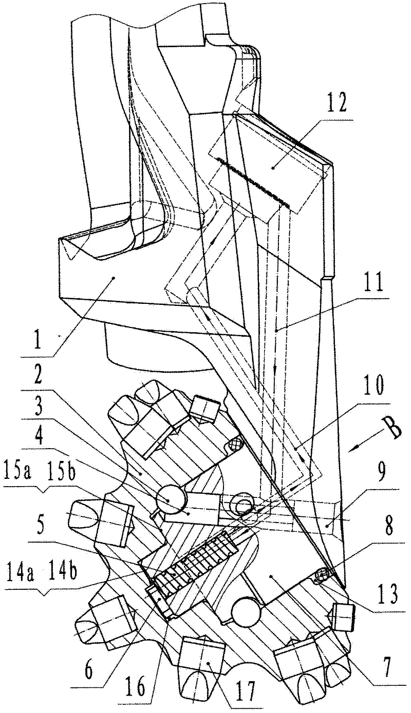
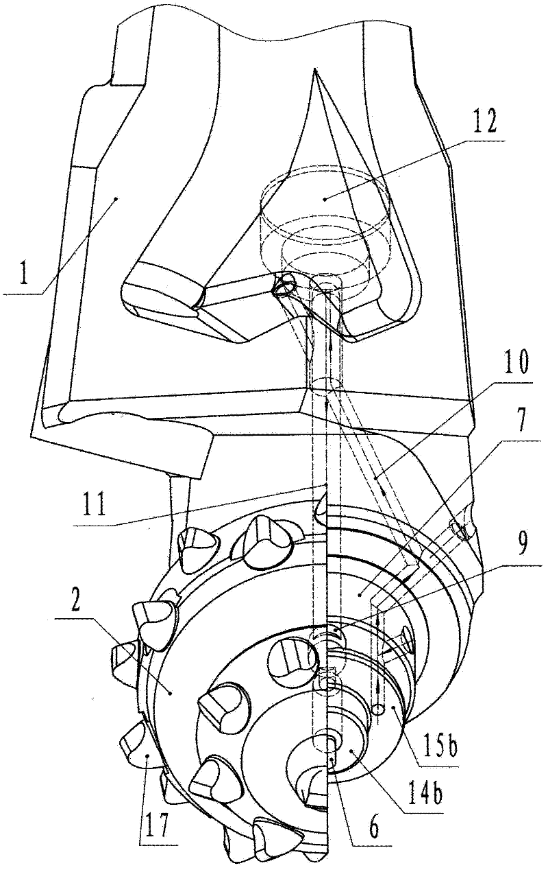
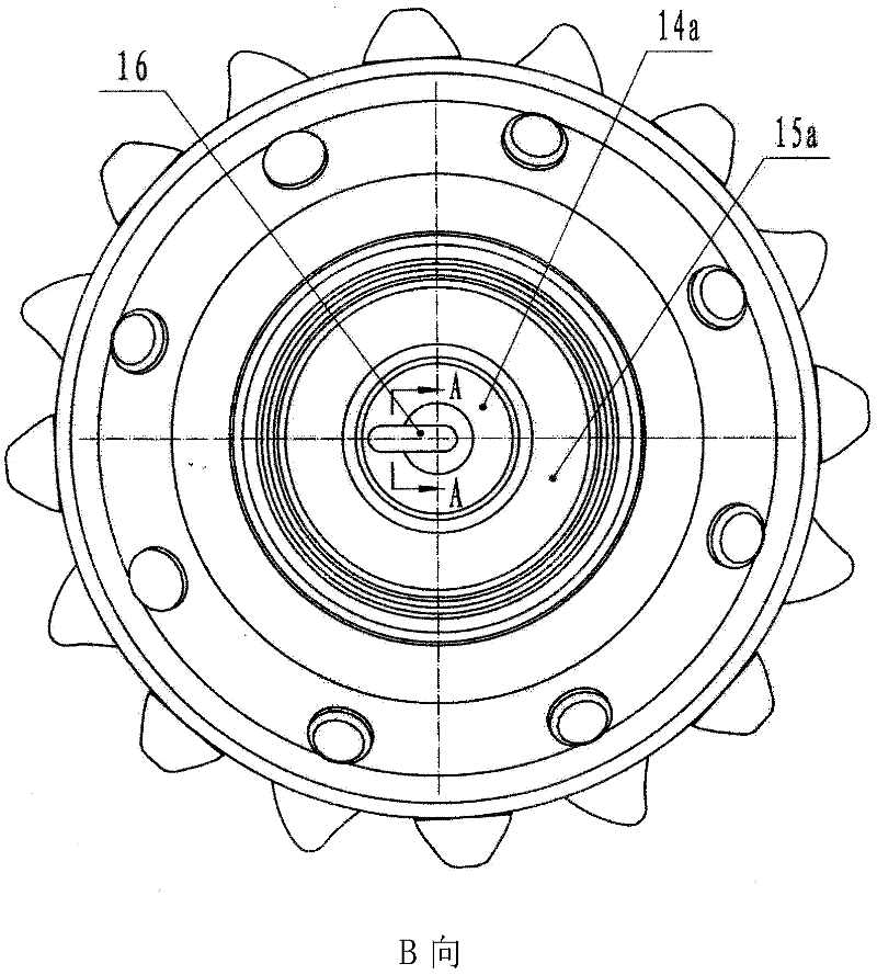
[0017] Embodiment 1: The end of the tooth palm (1) is provided with a tooth palm small shaft (7), the cone (2) is slidably installed on the tooth palm small shaft (7), and the cone (2) is fitted with an interference fit drill The teeth (17), the locking steel balls (3) are installed between the cone (2) and the small shaft of the tooth palm (7) with clearance fit, the plug pin (4) is fixed in the plug pin hole (9) with a transition fit, and the teeth The back of the palm (1) is provided with a sealed oil storage hole (12), the sealing ring (8) is installed on the root of the small shaft (7) of the tooth palm, and the cone (2) is provided with a cone thrust surface (14a) and a tooth Wheel thrust surface (15a), tooth palm (1) is provided with tooth palm thrust surface (14b) and tooth palm thrust surface (15b), tooth wheel thrust surface (14a) and tooth palm thrust surface (14b ) is a clearance fit; the gear thrust surface (15a) and the tooth palm thrust surface (15b) are tangent...

Embodiment 2

[0018] Embodiment two: a small shaft oil pump (5) is installed on the top of the small shaft of the tooth palm (7), the small shaft oil pump (5) is a plunger type, and the center line of the small shaft oil pump (5) is connected with the small shaft of the tooth palm (7) The center line of the small shaft oil pump (5) is arranged parallel to the center line, and the end of the small shaft oil pump (5) is provided with an oil pump transmission key (6), and the oil pump transmission key (6) automatically slides into the power groove (16) on the thrust surface (14a) of the cone due to the elastic force Inside, the section shape of the power groove (16) is trapezoidal, and the oil inlet passage (11) and the oil return passage (10) are arranged on the tooth palm (1) and are connected to the bearing chamber (13) and the sealed oil storage hole (12) in branches, The bearing cavity (13) and the sealed oil storage hole (12) are filled with lubricating grease, and one of the inlets of th...

Embodiment 3

[0019] Embodiment 3: The oil pump transmission key (6) provided at the end of the small shaft oil pump (5) is installed in the power groove (16) on the thrust surface (14a) of the gear wheel, and the cross-sectional shape of the power groove (16) is an arc shape, the small shaft oil pump (5) is a plunger type, the center line of the small shaft oil pump (5) and the center line of the small shaft of the tooth palm (7) are arranged in different planes, and the oil inlet channel (11) and The oil return channel (10) is connected to the bearing cavity (13) and the sealed oil storage hole (12) in a branch way, and the bearing cavity (13) and the sealed oil storage hole (12) are filled with grease, and the oil return channel (10) One of the inlets is located on the thrust surface (15a) of the cone.

[0020] The small shaft oil pump of the present invention is a screw pump. The center line of the pump coincides with the center line of the small shaft of the tooth palm. The revolution ...


PUM


Abstract

The invention provides a dynamic pressure circulating lubrication roller bit to overcome defects of the traditional lubrication system roller bit. The technical scheme is that: the end part of a palm is provided with a palm small shaft; the back of the palm is provided with a sealing oil storage hole; the top end of the palm small shaft is provided with a small shaft oil pump; and the palm is provided with an oil inlet channel and an oil outlet channel which are connected with a bearing chamber and the sealing oil storage hole. A lubrication dead zone at a sealing ring is eliminated, so that the end part of a plug is more easily seamlessly fitted with a runway of a locking steel ball, and the safety factor of the bit is improved; the traditional pressureless lubrication is changed into pressure lubrication, the dynamic pressure of fluid can timely repair a broken lubricating grease oil film, a pressure-bearing surface of a journal of the bit is supplemented with bit grease instantly, and a bearing cannot be quickly worn due to lubrication failure; and the service life of the bit is greatly prolonged, the rotating speed of the bit can be not under control, and the bit can better meet the requirement of high-pressure high-speed drilling in modern times and even in the future.

Description

technical field [0001] The invention relates to a roller cone bit, in particular to a dynamic pressure circulation lubrication roller cone bit, which realizes the dynamic pressure circulation of lubricating grease and belongs to the field of drilling tools. Background technique [0002] Roller cone bits are widely used in petroleum, natural gas, geology, coal fields, hydrological exploration and mining. Modern advanced drilling technology and equipment, pursuing safe and fast well completion process, the roller cone bit has the advantage of strong adaptability to the formation, and its position in the drilling and production tool cannot be replaced. The main reason for the failure and scrapping of roller cone bits is generally due to the chain reaction of poor lubrication. Poor lubrication is directly reflected in the premature fatigue of the bearing sliding pair or rolling pair, and the bearing cannot withstand high drilling pressure and high speed, resulting in a signific...

Claims


Application Information

Patent Timeline
IPC IPC(8): E21B10/24
Inventor 尚明刘新军
Owner 三原石油钻头厂
Learn More