
Metal-based cable-like distributed optical fiber sensor

A distributed sensor and distributed optical fiber technology, applied in the field of sensors, can solve the problems of fiber optic sensor application limitations, cable body monitoring difficulties, etc., and achieve the effects of improving survival rate and sensitivity, improving timeliness, and convenient installation

Inactive Publication Date: 2011-12-21
SUZHOU NANZEE SENSING TECH
View PDF3 Cites 21 Cited by
  • Summary
  • Abstract
  • Description
  • Claims
  • Application Information

AI Technical Summary

Problems solved by technology

[0006] The purpose of this invention is: (1) to solve the problem that the application of optical fiber sensors in the field of engineering monitoring is greatly limited, to overcome many shortcomings in the application of existing technologies, to carry out special packaging and protection for ordinary optical fibers, and to form a convenient installation, tensile strength The high-strength tight-buffered distributed sensing optical cable greatly improves the effectiveness, sensitivity and convenience of distributed optical fiber sensing technology in the field of engineering detection
(2) By implanting the optical fiber into the cable body, the monitoring of the internal force and temperature distribution of the cable itself is realized, which solves the problem of difficult monitoring of the cable body

Method used


Image

  • Metal-based cable-like distributed optical fiber sensor
  • Metal-based cable-like distributed optical fiber sensor
  • Metal-based cable-like distributed optical fiber sensor

Examples


Embodiment Construction

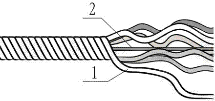
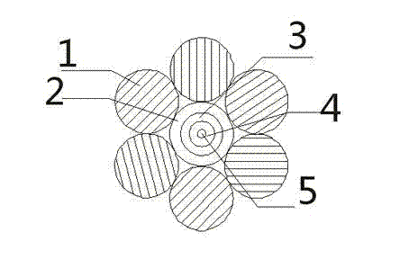
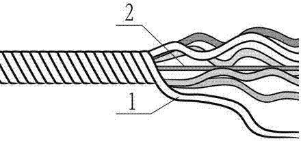
[0024] The metal cord-like material has a certain strength and meets certain requirements of ductility, deformability, machinability and corrosion resistance. The metal wires are steel wires, or metal wires made of metals such as copper, aluminum, and stainless steel. As shown in the figure: 1 steel wire bundle, 2 sheathed optical fiber, 3 coating layer, 4 cladding layer, 5 optical fiber core. Its implementation process is:

[0025] (1) Preparation of sensing fiber core

[0026] The sensing fiber core used in the present invention is common single-mode or multimode fiber core, tight package structure, and its diameter is 1 / 3 of the desired cable diameter, or slightly larger, so that can guarantee internal fiber core and The outer metal wires are in close contact and deform simultaneously. The outer cladding of the optical fiber has a certain degree of elasticity, which can buffer the external pressure and prevent the core from being squeezed and damaged during the strand...


PUM


Abstract

Metal-based cable-shaped distributed optical fiber sensor, the central sensing fiber with a sheath is twisted and wrapped around the core by six surrounding metal wires to form a metal-based cable distributed optical fiber sensor. In particular, the sensing optical fiber with the sheath has the same diameter as the metal wire, and is in tight contact with the surrounding 6 metal wires. The outer steel wire bundle is wrapped around the central sensing optical fiber in a helical form, and the central sensing optical fiber is kept straight and not entangled. The optical fiber (cable) located in the center of the cable is tightly wound helically by six steel wires with matching diameters to form a metal cable body that can directly sense strain and temperature. The sensing optical cable of this structure not only senses the close contact between the optical fiber and the peripheral reinforced steel wire and the object to be measured, but also realizes the distributed monitoring of the stress and strain of the steel wire and the surrounding object to be monitored, and uses high-strength steel wire to protect the delicate The fragile sensing optical fiber has significantly improved its tensile strength, impact resistance and bending resistance.

Description

technical field [0001] The invention relates to distributed optical fiber sensing technology and belongs to the technical field of sensors. Background technique [0002] Distributed optical fiber sensing technology is a new type of monitoring technology and method developed internationally in recent years. In actual monitoring applications, it not only has the advantages of anti-electromagnetic interference, corrosion resistance, good durability, small size, and light weight inherent in optical fibers. , also has many advantages such as distributed and long distance, and is increasingly favored by scientific and technological personnel in the field of engineering monitoring. Distributed optical fiber sensing technology is widely used because of its ability to extract relevant information in a wide range of measurement fields, and has achieved breakthroughs in many measurement problems in the current measurement field. For example, distributed strain sensors can currently be ...

Claims


Application Information

Patent Timeline
IPC IPC(8): G01B11/16G01K11/32G01K11/322G01K11/324
Inventor 魏广庆施斌胡盛卢俊武卢毅席均
Owner SUZHOU NANZEE SENSING TECH
Learn More