Distributed optical fiber sensing device for simultaneously detecting Brillouin scattering and Raman scattering

A distributed optical fiber and sensing device technology, applied in the direction of measuring devices, using optical devices, using optical devices to transmit sensing components, etc., can solve problems that affect measurement accuracy, limit measurement distance, and difficult to integrate optical fiber networks, etc., to achieve Improve detection accuracy, improve detection signal-to-noise ratio, and extend the effect of sensing distance

Active Publication Date: 2012-01-11
WUHAN KANGTESHENGSI PHOTOELECTRIC TECH
View PDF5 Cites 27 Cited by
  • Summary
  • Abstract
  • Description
  • Claims
  • Application Information

AI Technical Summary

Problems solved by technology

[0005] 1. Two-parameter measurement method of scattered light intensity and frequency shift (J. Smith et al., Simultaneous distributed strain and temperature measurement”, Appl. Opt, 38 :5372-5377, 1999), this type of measurement method using light intensity The measurement distance is limited, and the light intensity is easily disturbed by the outside world, which affects the measurement accuracy
[0006] 2. Special optical fiber method (M. Alahbabi, Y. T. Cho, and T. P. Newson. “Comparison of the methods for discriminating temperature and strain in spontaneous Brillouin-based distributed sensors”, Optics Letters, 2004, 29(1): 26~28) , this type of method is based on special optical fiber, it is difficult to integrate with the existing optical fiber network, which limits its scope of application
However, the light source used by the Raman scattering distributed fiber optic sensor is generally a high-power pulse light source greater than the watt level, while the Brillouin scattering distributed fiber optic sensor is limited by the stimulated Brillouin scattering effect, generally less than the watt level. Low-power pulsed light source, so it is difficult to combine both sensors in one device under normal circumstances

Method used


Image

  • Distributed optical fiber sensing device for simultaneously detecting Brillouin scattering and Raman scattering
  • Distributed optical fiber sensing device for simultaneously detecting Brillouin scattering and Raman scattering

Examples


Embodiment Construction

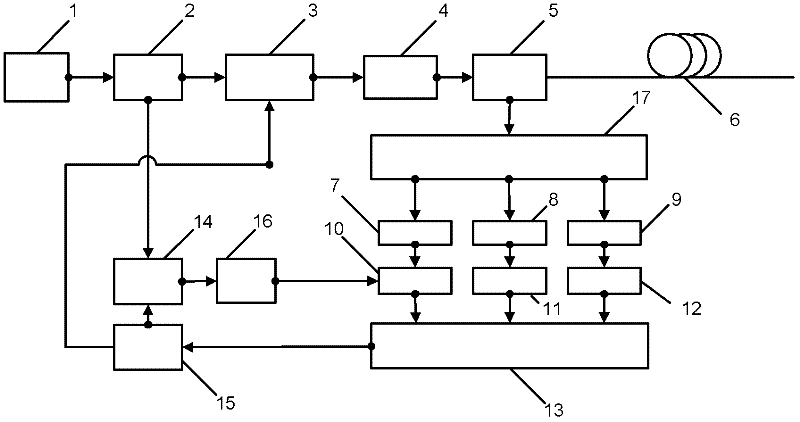
[0039] refer to figure 1 , the present invention is a distributed optical fiber sensing device for simultaneous detection of Brillouin and Raman, a narrow-band light source 1, two optical couplers 2, 5, a coded pulse light modulator 3, an optical amplifier 4, and three optical filters 7, 8, 9, three photodetectors 10, 11, 12, electrical decoder 13, optical frequency shifter 14, electronic processor 15, optical polarization controller 16, wavelength division multiplexer 17. The light emitted by the narrowband light source 1 is divided into two paths by the optical coupler 2 , one output end is connected to an input end of the coded pulse light modulator 3 , and the other output end is connected to an input end of the optical frequency shifter 14 . The output terminal of the optical frequency shift generating device 14 is connected to the input terminal of the polarization controller 16 , and the output terminal of the optical polarization controller 16 is connected to an in...


PUM


Abstract

The invention aims to provide a distributed optical fiber sensing device for simultaneously detecting Brillouin scattering and Raman scattering, which is characterized by comprising a narrow band light source, two optical couplers, a coded pulse optical modulator, an optical amplifier, three optical fibers, three photoelectric detectors, an electric decoder, an optical frequency shifter, an electronic processor, a light polarization controller and a wavelength division multiplexer. The distributed optical fiber sensing device has the advantages that the Brillouin scattering distributed optical fiber sensing and the Raman scattering distributed optical fiber sensing are simultaneously realized in the same device system; the Brillouin scattering is subjected to temperature compensation by the Raman scattering, so that double parameters of the temperature and the strain are simultaneously measured; and due to the utilization of a coding modulation and optical coherent detection technology, the detectable signal-to-noise ratio is improved, the sensing distance is lengthened and the detection accuracy is improved.

Description

technical field [0001] The invention relates to a Brillouin and Raman distributed optical fiber sensor and belongs to the technical field of optical fiber sensing. Background technique [0002] Due to its advantages of anti-electromagnetic interference, corrosion resistance and electrical insulation, the distributed optical fiber sensor can perform one-dimensional online monitoring of the measured object without blind spots, and has a wide application prospect. Raman scattering distributed fiber optic sensors and Brillouin scattering distributed fiber optic sensors are two main long-distance distributed fiber optic sensors, both of which have their own advantages and disadvantages and implementation technologies. In some applications, these two distributed optical fiber sensors may be needed at the same time, but how to realize the organic combination of these two sensors, that is, the two sensors can share the main optical devices and electronic processing devices such as l...

Claims


Application Information

Patent Timeline
Patent Type & Authority Applications(China)
IPC IPC(8): G01D5/353G01B11/16G01K11/32G01K11/322G01K11/324
Inventor 宋牟平谢杭汤贇张伟峰励志成沈逸铭辛凯
Owner WUHAN KANGTESHENGSI PHOTOELECTRIC TECH
Why Eureka
Try Eureka