Antenna amplifier device and antenna device provided in mobile object

A technology for antenna amplifiers and moving bodies, applied to antennas on movable objects, amplifiers with semiconductor devices/discharge tubes, components of amplifiers, etc., can solve the problem of increased noise levels and increased noise voltages, etc. question

Inactive Publication Date: 2012-01-11
FUJITSU GENERAL LTD
View PDF6 Cites 5 Cited by
  • Summary
  • Abstract
  • Description
  • Claims
  • Application Information

AI Technical Summary

Problems solved by technology

[0009] However, if the signal source impedance is high by using a booster coil or the like, the signal level is improved, but the noise voltage is also increased due to the influence of the equivalent noise resistance of the FET itself, so there is a noise level also increase the problem

Method used


Image

  • Antenna amplifier device and antenna device provided in mobile object
  • Antenna amplifier device and antenna device provided in mobile object
  • Antenna amplifier device and antenna device provided in mobile object

Examples


Embodiment Construction

[0034] Next, the antenna amplifier device of the present invention and an antenna device incorporating the antenna amplifier device will be described.

[0035] Such as Figure 7A , Figure 7B As shown, multiple antennas for receiving broadcast waves with different signal systems, such as an antenna for receiving AM broadcast, an antenna for receiving FM broadcast, and an antenna for receiving digital TV, are installed on the rear glass of a mobile vehicle. A, An antenna device 14 is provided near each antenna. In addition, in Figure 7A , Figure 7B In , it is roughly described that the antennas A of the three systems are installed in one area, but the installation areas may differ from one another.

[0036] A controller 60 for audio equipment is arranged at the front left of the driver's seat, and a head unit 40 as an integrated receiver is arranged near it. Furthermore, the antenna device 14 and the head unit 40 are connected by two data transmission lines L (L1, L2) an...


PUM


Abstract

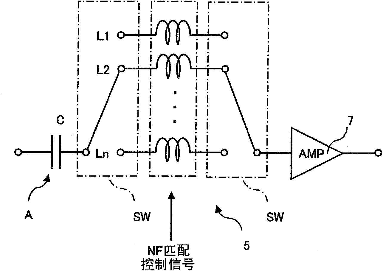
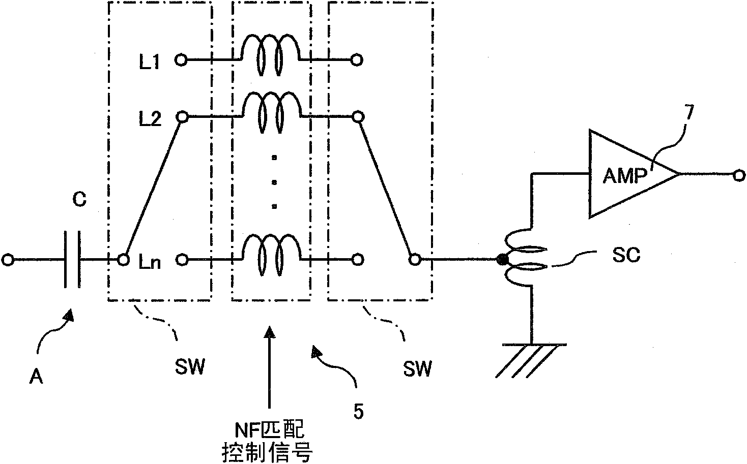
Even when an input is weak, an antenna amplifier device may achieve a high sensitivity while reducing a noise factor (NF). The antenna amplifier device includes an amplification circuit 7 for amplifying a high frequency signal received by an antenna A, and an NF matching circuit 5 provided between the amplification circuit 7 and the antenna A of which input impedance has a capacitance, the NF matching circuit 5 for switching the input impedance to the amplification circuit 7 in accordance with a reception frequency. The NF matching circuit 5 includes a plurality of coils having different inductances, and at least one switch SW for connecting one of the coils, selected in accordance with the reception frequency, between the antenna A and the amplification circuit 7. A step-up coil SC is interposed between the NF matching circuit 5 and the amplification circuit 7.

Description

technical field [0001] The present invention relates to an antenna amplifier device and an antenna device. Background technique [0002] In receiving systems for broadcast waves such as AM broadcasting, FM broadcasting, and digital TV broadcasting mounted on mobile objects, antenna amplifiers are used to improve transmission loss by matching the impedance between the antenna and audio equipment, and to prevent a decrease in the S / N ratio. device. [0003] Japanese Laid-Open Publication No. Hei 10-209897 discloses a variable-tunable antenna device having an antenna element having a length of 1 / 4 wavelength of the receiving frequency and always exhibiting Optimal VSWR. This variable tuning antenna device includes an LC series resonant circuit inserted between the base end of the receiving antenna and the antenna input end of the receiver. [0004] In addition, the LC series resonant circuit includes an electronic variable capacitance element and an induction element, and th...

Claims


Application Information

Patent Timeline
Patent Type & Authority Applications(China)
IPC IPC(8): H04B1/18H01Q1/27
CPCH03F3/195H03F2200/451H03F1/565H04B1/18H03F1/26H03F2200/222H03F2200/165
Inventor 河合健史高山一男
Owner FUJITSU GENERAL LTD
Why Eureka
Try Eureka