Automatic control device for rotation of blast furnace chute

An automatic control device and chute technology, applied in the control of electromechanical transmission, motor generator control, electronic commutation motor control, etc., can solve problems such as hidden dangers of personal safety of mechanical equipment, inability to meet control requirements, and unsatisfactory control accuracy. , to achieve the effect of reducing interference and impact of mechanical equipment, reducing exhaust gas and soot emissions, saving electricity and coke

Inactive Publication Date: 2012-01-18
CHINA THIRD METALLURGICAL GROUP ELECTRICAL INSTALLATION ENG
View PDF1 Cites 4 Cited by
  • Summary
  • Abstract
  • Description
  • Claims
  • Application Information

AI Technical Summary

Problems solved by technology

Since the bellless furnace top charging equipment introduced by Luxembourg Paul Wurth Company in the early 1970s replaced the traditional bell furnace top, the rotation of the chute has been driven by a wound rotor asynchronous motor (or DC machine). The control mode is not only a waste of energy, but also far from meeting the requirements of modern industry
Motor frequency conversion control has the advantage of flexible control, but due to the imperfect corresponding protection system and unsatisfactory control accuracy, it brings great safety hazards to mechanical equipment and personal safety, and cannot meet the control requirements of normal production

Method used


Image

  • Automatic control device for rotation of blast furnace chute
  • Automatic control device for rotation of blast furnace chute

Examples


Embodiment Construction

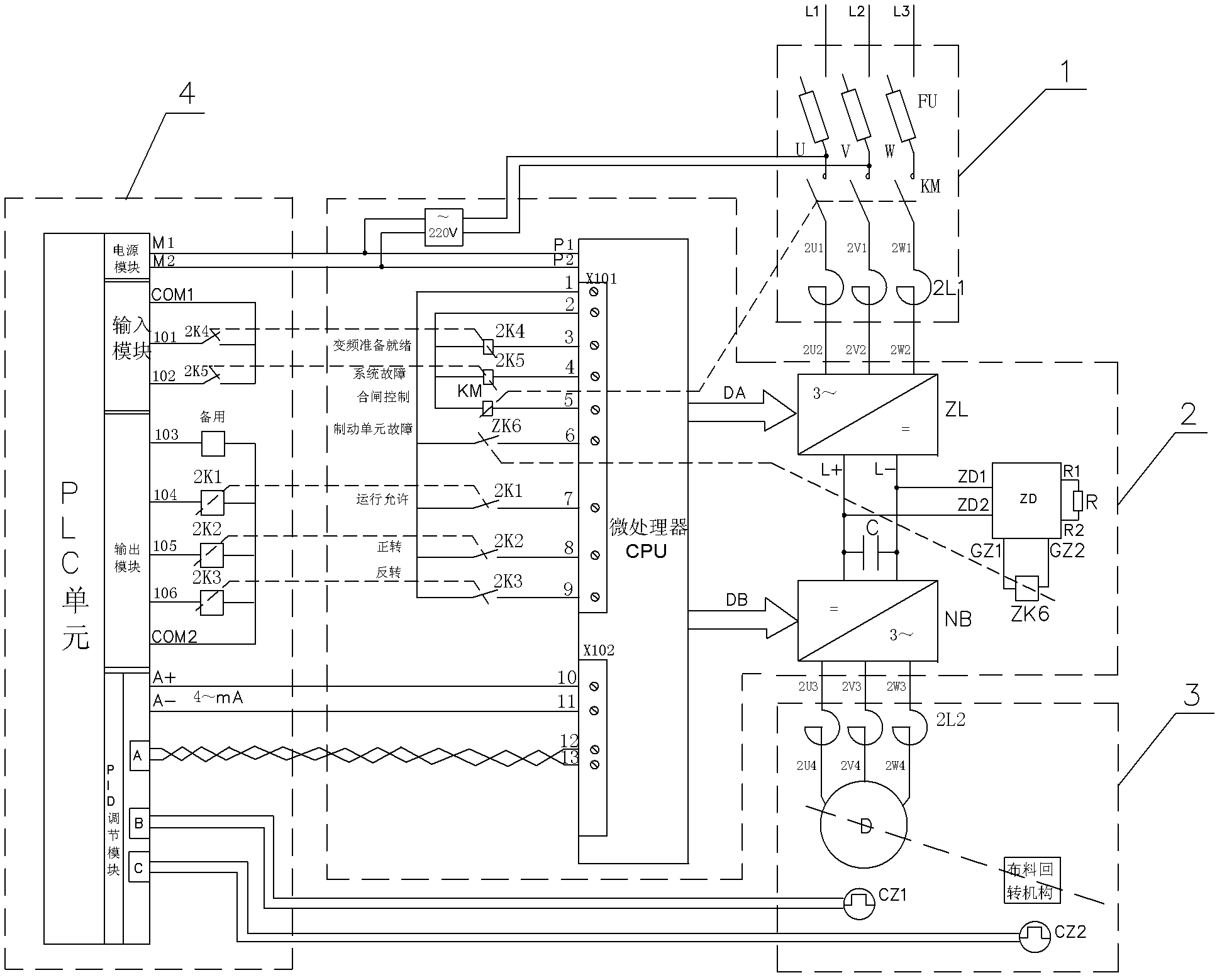
[0017] The specific embodiment of the present invention will be further described below in conjunction with accompanying drawing:

[0018] See figure 1 , is a structural schematic diagram of an embodiment of an automatic control device for blast furnace chute rotation in the present invention, including an input unit 1, a frequency conversion drive unit 2, an execution unit 3 and a PLC control unit 4, and the input unit 1 is connected to the frequency conversion drive unit 2 and the execution unit 3 in sequence , the PLC control unit 4 is connected with the variable frequency drive unit 2, and the input unit 1 includes a fast fuse FU with a short-circuit fast-fuse function, a contactor KM with an automatic control and power cut-off function, and a reactor-2L1 with a filter and compensation function , the three-phase power supply L1, L2, L3 are sequentially connected with the fast fuse FU, the contactor KM and the reactor-2L1;

[0019] The variable frequency drive unit 2 inclu...


PUM


Abstract

Relating to the technical field of chute automation control of a blast furnace distributing device, the invention especially relates to an automatic control device for rotation of a blast furnace chute. The device is characterized by comprising an input unit, a frequency conversion driving unit, an execution unit and a PLC (programmable logic controller) control unit. The input unit is connected to the frequency conversion driving unit and the execution unit in order, and the PLC control unit is in connection with the frequency conversion driving unit. The input unit consists of a rapid fuse, a contactor and a reactor 1 which are connected to a three-phase power supply in order. Compared with the prior art, the invention, by combining a PID (proportion integration differentiation) closed loop vector control technology and a PLC programming control technology, converts a speed instruction to an analog signal of 4-20mA so as to control the rotation speed of the chute, thus the system can have great torque and rapidity, and also can reach an ideal degree of accuracy. Therefore, the utilization coefficient of the blast furnace is raised, and the discharge of exhaust gases and flue dust can be reduced.

Description

technical field [0001] The invention relates to the technical field of chute automatic control of a blast furnace distributor, in particular to an automatic control device for blast furnace chute rotation. Background technique [0002] In view of the current global energy shortage and the reality that environmental pollution is becoming more and more serious, the country attaches great importance to energy conservation and environmental protection. Iron and steel enterprises are large energy consumers, consuming 40% of the world's energy every year, and blast furnace ironmaking is energy-consuming in iron and steel enterprises. Importantly, the performance of the material distribution system in blast furnace ironmaking is directly related to whether the energy is fully utilized, the blast furnace utilization factor and the exhaust gas and dust emission indicators. In the electromechanical integrated equipment for blast furnace material distribution, it is often required to c...

Claims


Application Information

Patent Timeline
Patent Type & Authority Applications(China)
IPC IPC(8): C21B7/00G05B19/05H02P21/00
Inventor 田印福
Owner CHINA THIRD METALLURGICAL GROUP ELECTRICAL INSTALLATION ENG
Why Eureka
Try Eureka