Orientated-growth latticed high-performance carbon nano-tube field emission array and preparation method

A carbon nanotube and grid-like technology, which is applied in the field of field emission cathode preparation, can solve problems such as area waste, achieve the effects of improving structural stability, enhancing edge effects, and increasing emission current density

Inactive Publication Date: 2013-12-04
上海康众光电科技有限公司
View PDF2 Cites 0 Cited by
  • Summary
  • Abstract
  • Description
  • Claims
  • Application Information

AI Technical Summary

Problems solved by technology

Since the field emission of the carbon nanotube array is mainly concentrated on the edge, if the area of ​​the pattern unit in the carbon nanotube array is too large, the area is wasted

Method used


Image

  • Orientated-growth latticed high-performance carbon nano-tube field emission array and preparation method
  • Orientated-growth latticed high-performance carbon nano-tube field emission array and preparation method
  • Orientated-growth latticed high-performance carbon nano-tube field emission array and preparation method

Examples


Embodiment

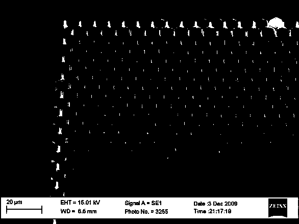
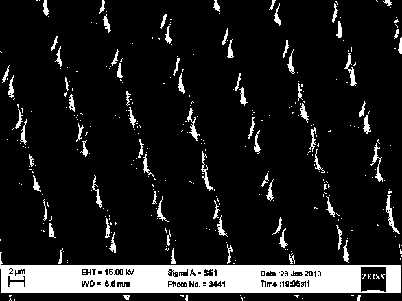
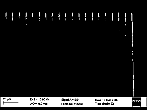
[0020] Embodiment, the preparation process of the high-performance grid-mounted carbon nanotube array is as follows:

[0021] (1) First, select a heavily doped silicon wafer as the substrate, wash the silicon wafer in acetone (acetone) and isopropanol (IPA) for two minutes to remove surface organic matter and other impurities, bake to 180°C and keep Two minutes to remove moisture from the surface.

[0022] (2) Then spin-coat a layer of electron beam photoresist on the surface, and harden the film at a temperature of 180°C for 90 seconds.

[0023] (3) The photoresist is photoetched to form a grid pattern, and after development, a photoresist mask with a pattern is prepared.

[0024] (4) Then sputter a catalyst film on the surface of the sample by magnetron sputtering. The catalyst here is composed of two layers of films, the lower layer is an Al film with a thickness of 10nm, and the upper layer is a Fe film with a thickness of 1nm.

[0025] (5) Stripping, the sample is immer...


PUM

PropertyMeasurementUnit
thicknessaaaaaaaaaa
thicknessaaaaaaaaaa

Abstract

The invention discloses an orientated-growth latticed high-performance carbon nano-tube field emission array, which comprises a conductive substrate and latticed orientated carbon nano-tube arrays grown on the substrate, wherein the carbon nano-tube arrays are distributed into a latticed shape and form an integral structure. By the technical scheme, the structural stability of small-size carbon nano-tube arrays is improved, the edge effect of the carbon nano-tube arrays is enhanced, and then a turn-on electric field and a threshold electric field are reduced to improve the emission current density. The orientated-growth latticed high-performance carbon nano-tube field emission array is suitable for field emission devices having high requirements on current emission performance, such as electron sources in an X ray source, a microwave amplifier, a field emission scanning electron microscope and the like.

Description

technical field [0001] The invention relates to a field emission element and a preparation method, in particular to a field emission cathode preparation method. technical background [0002] Carbon nanotubes are one of the main materials for field emission device research at present, and have very bright prospects. All major scientific research institutions in the world are actively working hard to realize the practical application and industrialization of carbon nanotubes in field emission devices. In the current research field of carbon nanotubes and related fields, new structures, materials and process methods are still being explored. On the other hand, there are already dozens of emission materials and device structures. Exploring the working mechanism of these nanotube material cold cathodes and fully exploring and utilizing the potential performance of existing device structures are still very important research contents. [0003] In the preparation of large current...

Claims


Application Information

Patent Timeline
Patent Type & Authority Patents(China)
IPC IPC(8): H01J1/304
Inventor 张研李驰
Owner 上海康众光电科技有限公司
Why Eureka
Try Eureka