Combined cycle generating system for improving heat source usage efficiency

A technology of combined cycle power generation and high efficiency, applied in the direction of machines/engines, steam engine devices, mechanical equipment, etc., can solve problems such as inability to absorb or discharge, and inability to extract heat, and achieve low power generation costs, wide application range, and stable systems.

Inactive Publication Date: 2012-02-01
SHANGHAI SHENGHE NEW ENERGY RESOURCES SCI & TECH
View PDF6 Cites 19 Cited by
  • Summary
  • Abstract
  • Description
  • Claims
  • Application Information

AI Technical Summary

Problems solved by technology

[0004] Through the above process, it can be found that water is isothermally evaporated in the boiler and condensed in the condenser. In the process of water obtaining heat from the heat source and the cold source, it is limited by the isothermal endothermic and exothermic characteristics of

Method used


Image

  • Combined cycle generating system for improving heat source usage efficiency
  • Combined cycle generating system for improving heat source usage efficiency
  • Combined cycle generating system for improving heat source usage efficiency

Examples


Embodiment 1

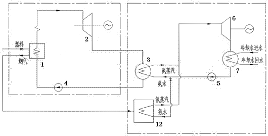
[0014] When the heat of the cooling water and the heat source of the steam boiler need to be fully utilized at the same time, such as figure 1 The system shown includes steam boiler 1, steam boiler 1 is connected in series with steam turbine 2, condenser 3 and feed water pump 4, feed water pump 4 is connected back to steam boiler 1 to form a cycle, and the cooling water inlet of condenser 3 is connected to ammonia feed Pump 5, whose cooling water outlet is connected to ammonia water vapor-liquid separator 6 (that is, ammonia steam turbine generator set), ammonia water vapor-liquid separator 6 is connected to ammonia feed pump 5 through ammonia water absorption / condenser 7 to form a cycle, and then Connect the hot side outlet of the steam boiler 1 to the hot side of the ammonia water evaporator 12, connect the cold side inlet of the ammonia water evaporator 12 to the ammonia feed pump 5, and connect the cold side outlet of the ammonia water evaporator 12 to the ammonia water vap...

Embodiment 2

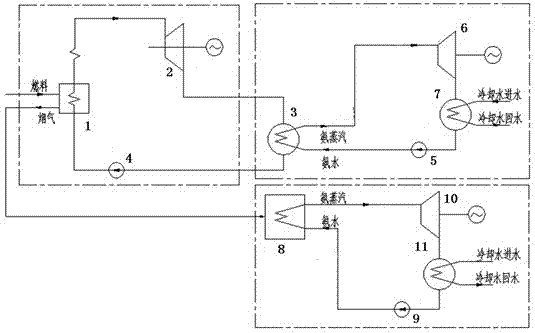
[0017] can also be used as figure 2 As shown in the system, the system includes a steam boiler 1. The steam boiler 1 is connected in series with a steam turbine 2, a condenser 3 and a feed water pump 4. The feed water pump 4 is connected back to the steam boiler 1 to form a cycle. The cooling water inlet of the condenser 3 is connected to Ammonia feed pump 5, whose cooling water outlet is connected to ammonia water vapor-liquid separator 6, ammonia water vapor-liquid separator 6 is connected to ammonia feed pump 5 through ammonia water absorption / condenser 7 to form a circulation, and then the hot side outlet of steam boiler 1 The end is connected to the hot side of the first ammonia water evaporator 8, the cold side inlet end of the first ammonia water evaporator 8 is connected to the first ammonia feeding pump 9, and the cold side outlet end of the first ammonia water evaporator 8 is connected to the first ammonia water vapor The liquid separator 10 (that is, the ammonia st...


PUM


Abstract

The invention provides a combined cycle generating system for improving heat source usage efficiency, which comprises a steam boiler and an ammonia water evaporator, wherein the steam boiler is sequentially connected with a steam turbine, a condenser and a feed pump in series, and the feed pump is connected back to the stem boiler to form a rankine power cycle; and the ammonia water evaporator is sequentially connected with an ammonia water gas liquid separator, an ammonia water absorbing/condensing device, an ammonia storage tank and an ammonia feeding pump in series, and the ammonia feeding pump is connected back to the ammonia water evaporator to form a kalina power cycle. The combined cycle generating system is characterized in that a heat side outlet of the steam boiler is connected to a heat side inlet of the ammonia water evaporator, or a cold side outlet of the condenser is connected to the heat side inlet of the ammonia water evaporator. The combined cycle generating system provided by the invention has the advantages that: the equipment is simple, the arrangement is compact, complete production can be carried out, and the cost is lower; a kalina power cycle device has mature technology and lower cost; the kalina power cycle has high cycle efficiency at the low temperature; and the rankine-kalina combined cycle generating system is stable, safe and reliable, can be unmanned, has long maintenance period, low maintenance cost, low generating cost and wide applicable scope, and is particularly applied to deep usage of waste heat in a conventional thermal power plant.

Description

technical field [0001] The invention relates to a Rankine-Karina combined cycle power generation system, which is a system for improving the heat source utilization efficiency of a steam power plant. Background technique [0002] The earliest power machine used in the industry was a steam power plant with water vapor as the working medium. Water in a steam power plant is sometimes in a liquid state and sometimes in a gaseous state. For example, in a steam boiler, liquid water is vaporized to produce steam. After the steam turbine expands and does work, it enters the condenser and condenses into water before returning to the boiler. It can maintain a constant temperature, and because the combustion products do not participate in the cycle, the steam power plant can use various fuels, such as coal, residual oil, and even combustible garbage. [0003] The Rankine cycle is a simple steam power plant cycle, and its process is roughly as follows: fuel is burned in a steam boiler ...

Claims


Application Information

Patent Timeline
IPC IPC(8): F01K11/00F01K25/10F01K23/04F01K27/00
Inventor 张高佐郭佳戴军王春莉
Owner SHANGHAI SHENGHE NEW ENERGY RESOURCES SCI & TECH
Why Eureka
Try Eureka