Digital control device and method for LLC (logical link control) synchronously-rectified resonant converter

A technology of resonant converter and control device, which is applied in the direction of output power conversion device, conversion of DC power input to DC power output, conversion of AC power input to DC power output, etc. Susceptible to interference, current signal delay and other issues

Inactive Publication Date: 2012-02-15
SHANGHAI UNIV
View PDF1 Cites 60 Cited by
  • Summary
  • Abstract
  • Description
  • Claims
  • Application Information

AI Technical Summary

Problems solved by technology

However, the current transformer has parasitic inductance, which is easy to delay the current signal and the turn-on signal. At the same time, the current transformer increases the cost and volume, and is easy to be interfered, so it is rarely used
[0009] When the LLC synchronous rectification resonant converter...

Method used


Image

  • Digital control device and method for LLC (logical link control) synchronously-rectified resonant converter
  • Digital control device and method for LLC (logical link control) synchronously-rectified resonant converter
  • Digital control device and method for LLC (logical link control) synchronously-rectified resonant converter

Examples


Embodiment 1

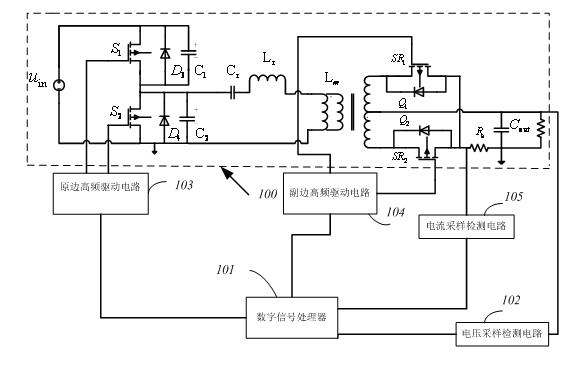
[0076] See attached figure 1 , a structural block diagram of a synchronous rectification control device for a digital LLC synchronous rectification resonant converter of the present invention, including a main circuit (100) and a corresponding control device. The control circuit includes a digital signal processor DSP (101), a primary side high frequency drive circuit (103), a current sampling detection circuit (105), a voltage sampling detection circuit (102) and a secondary side high frequency drive circuit ( 104).

[0077] The above-mentioned digital signal processor (101) judges the operating area of ​​the circuit according to the output voltage fed back by the voltage sampling detection circuit (102), and changes the values ​​of the two on-chip period registers respectively after three-pole and two-zero compensation to generate a high-frequency drive signal, And output to the high-frequency driving circuit (103) and (104) by the digital signal processor (101), the high-f...

Embodiment 2

[0094] see Image 6 , the control method of the digital LLC synchronous rectification resonant converter adopts the above-mentioned control device to control the above-mentioned circuit, and then it is characterized in that the control steps are as follows:

[0095] (1) Initialize the timer of the digital signal processor , set it as a comparison interrupt, make the circuit start with a constant duty cycle and a fixed frequency, and set the dead time as , Reduce the impact and electromagnetic interference on the circuit caused by frequency conversion startup. set high here port, to ensure the normal operation of the 555 timer;

[0096] (2) After entering the interrupt, judge whether the circuit is soft-started and over-current. If the circuit is working in the output over-current state, it will jump out of the interrupt and turn off the PWM output. If the circuit is working in the soft-starting state, it will continue to maintain a constant duty than fixed frequency sta...


PUM


Abstract

The invention relates to a digital control device and method for an LLC (logical link control) synchronously-rectified resonant converter. The device comprises a digital signal processor, a primary high-frequency driving circuit, a current sampling detection circuit, a voltage sampling detection circuit and a secondary high-frequency driving circuit, wherein the digital signal processor judges an operation area of a circuit according to an output voltage fed back by the voltage sampling detection circuit, after the circuit performs three-pole two-zero compensation, the values of an on-chip period register are respectively changed so as to generate high-frequency driving signals which are then output to the primary and secondary high-frequency driving circuits by the digital signal processor; the current sampling detection circuit detects a secondary output current which is then output to the digital signal processor, then the digital signal processor judges whether an overloading or overcurrent phenomenon (generated in the process of area switching) occurs according to the size of the current so as to cut off the primary and secondary high-frequency driving circuits in time. In the invention, the LLC resonant converter is subjected to the following digital control by a digital signal processing chip-peripheral timer combined circuit: the advanced conduction of secondary synchronous rectifying tubes is realized by the design of software/hardware auxiliary circuits, and the control on secondary driving signals is performed by adding a 555 timer, so the application of a timer in a DSP (digital signal processing) chip is reduced, thereby effectively solving the problem of conduction loss of synchronous rectifying tubes introduced in the process of underloading in the traditional control strategy; and the application of a PWM (pulse-width modulation) port of the digital signal processing chip is reduced, thereby improving the reliability of the whole device.

Description

technical field [0001] The invention belongs to the field of communication power supply and LED lighting, and in particular relates to a digital LLC synchronous rectification resonant converter control device and method. [0002] Background technique [0003] Compared with the traditional DCDC topology, the primary side MOS transistor of the LLC resonant converter can realize zero-voltage turn-on in a wider frequency range, and can improve its own efficiency with the increase of the primary side input voltage, which is more suitable for working in the power factor backend of the correction circuit. Therefore, the LLC resonant converter gradually replaces the traditional DCDC topology and is used in high-power applications. [0004] The traditional LLC synchronous rectification resonant converter generates resonance through resonant inductor, resonant capacitor and transformer to realize soft switching. [0005] The working state of the LLC synchronous rectification reson...

Claims


Application Information

Patent Timeline
IPC IPC(8): H02M7/217H02M3/335
CPCY02B70/10
Inventor 廖文高艳霞杨郑浩刘攀
Owner SHANGHAI UNIV
Why Eureka
Try Eureka