Clock calibration method based on FM (Frequency Modulation) radio data system

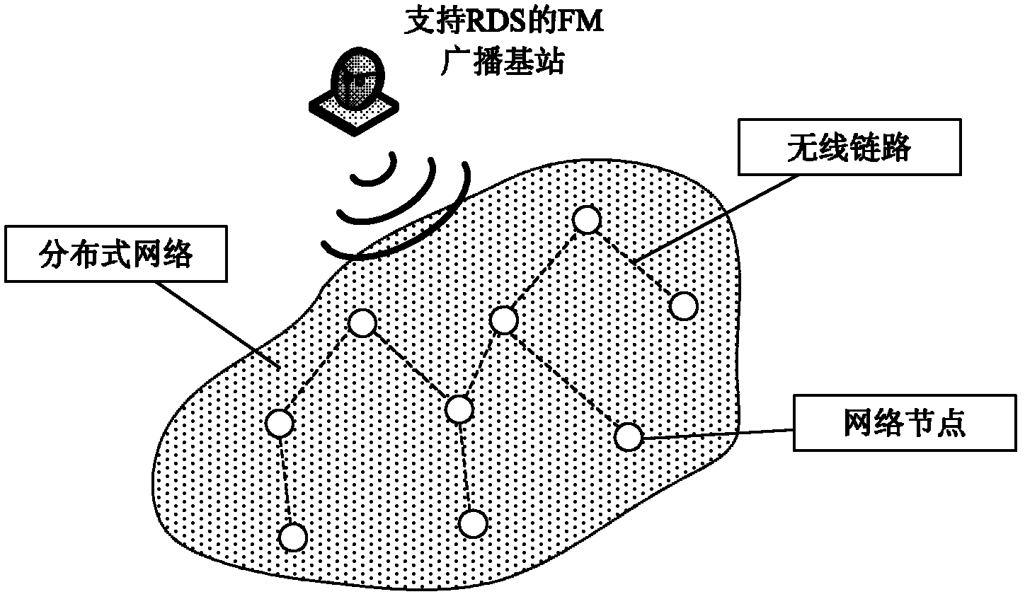
A broadcast data system and clock calibration technology, applied in broadcast service distribution, electrical components, synchronization devices, etc., can solve the problems of occupying communication bandwidth, GPS module consumes a lot of energy, and large node energy

Inactive Publication Date: 2012-02-15
INST OF SOFTWARE - CHINESE ACAD OF SCI
View PDF0 Cites 7 Cited by
  • Summary
  • Abstract
  • Description
  • Claims
  • Application Information

AI Technical Summary

Problems solved by technology

[0005] Among the existing clock synchronization protocols, message-based clock synchronization protocols rely on the flooding of control messages in the entire network to complete global clock synchronization. This process consumes a lot of node energy and occupies scarce communication bandwidth.
The clock synchronization based on the global signal can greatly reduce the communication between nodes and save bandwidth and energy consumption. Therefore, this method has attracted extensive attention of researchers in recent years, but the existing protocols have significant defects.
For example, the GPS module consumes a lot of energy and can only be used outdoors in an unobstructed environment; wide-area broadcast clock signals such as WWVB are only suitable for areas with high outdoor signal strength; clock synchronization protocols based on power lines can only cover power lines surrounding areas and are therefore only suitable for use indoors or around power lines

Method used


Image

  • Clock calibration method based on FM (Frequency Modulation) radio data system
  • Clock calibration method based on FM (Frequency Modulation) radio data system
  • Clock calibration method based on FM (Frequency Modulation) radio data system

Examples


Embodiment Construction

[0038] Such as Figure 4 , at the initial α 0 An offline estimated value can be taken. Usually, the theoretical value of the clock skew can be taken, that is, the ratio of the RDS clock frequency to the rated frequency of the crystal oscillator. In addition, when the system starts, set the initial node time c n (0)=0, then the calibration steps of the node are as follows:

[0039] Step 1: Start the node, and set the initial node clock to 0, and set the initial clock skew α 0 is the theoretical value, and the sleep cycle is T α (represented by the node clock), then the node FM chip sleeps;

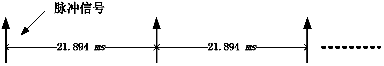
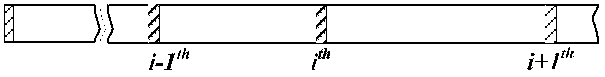
[0040] Step 2: When the node clock reaches the first sleep time T 0 , the FM chip starts to receive the signal and generates an RDS pulse, and records the current node clock c at the moment when the RDS pulse is generated n (i), predict the RDS clock c of the node at the calibration time r (i), calculate the clock skew of the current period by the previous formula (2), as shown in th...


PUM


Abstract

The invention relates to a clock calibration method based on an FM (Frequency Modulation) radio data system, which belongs to the field of wireless telecommunication. Each node of a distributed network is in the coverage area of the same FM base station. The method comprises the following steps that: 1) an FM receiving chip is arranged on each node; 2) RDS (Radio Data System) radio data is sent to each node by the FM base station; 3) the FM receiving chip of each node receives and analyzes the RDS radio data in calibration so as to generate an RDS pulse signal; and 4) a local clock is calibrated by each node according to the frequency of the RDS pulse signal so as to realize the time synchronization of each node. The RDS pulse frequency is used as the intermediate frequency to calibrate the local clock of the nodes, reduce communication between the nodes, and save bandwidth and energy consumption, so clock deflection is eliminated, and the effect of clock calibration is achieved.

Description

technical field [0001] The invention relates to a clock calibration method based on an FM broadcast data system, in particular to a sensor network clock calibration method based on an FM broadcast data system, and belongs to the field of wireless communication. Background technique [0002] A sensor network (Wireless Sensor Network, WSN) is a typical distributed system, each node in the network has certain computing, storage and communication capabilities, but due to the low working ability of a single node, most sensor networks Applications require the cooperation of multiple or even entire network nodes to complete a certain task. In this case, clock synchronization is often a prerequisite for successful cooperation between nodes, such as in animal habit monitoring applications (Alberto Cerpa, Jeremy Elson, Deborah Estrin, Lewis Girod, Michael Hamilton, and Jerry Zhao. Habitat monitoring : Application driver for wireless communications technology. In Proceedings of the 20...

Claims


Application Information

Patent Timeline
Patent Type & Authority Applications(China)
IPC IPC(8): H04W4/06H04W56/00
Inventor 孙利民李立群皇甫伟刘燕
Owner INST OF SOFTWARE - CHINESE ACAD OF SCI
Why Eureka
Try Eureka