Electrooptic modulator of periodically poled lithium niobate based on defect structure

An electro-optical modulator and periodic polarization technology, which is applied in the field of optoelectronics, can solve the problems of modulation bandwidth limitation, integration degree limitation, and large volume.

Inactive Publication Date: 2012-02-22
NANJING UNIV
View PDF1 Cites 7 Cited by
  • Summary
  • Abstract
  • Description
  • Claims
  • Application Information

AI Technical Summary

Problems solved by technology

However, due to the relatively large dielectric constant of lithium niobate crystals, the speed mismatch between microwaves and light waves is relatively large, and the modulation bandwidth is limited. To increase

Method used


Image

  • Electrooptic modulator of periodically poled lithium niobate based on defect structure
  • Electrooptic modulator of periodically poled lithium niobate based on defect structure
  • Electrooptic modulator of periodically poled lithium niobate based on defect structure

Examples


Embodiment 1

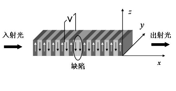
[0036] In order to ensure that the electro-optic modulator works in the communication band, the incident wavelength is set to 1550nm. According to the phase matching condition of the electro-optic effect, the period of the normal superlattice is l=20.48μm, and the reciprocal lattice vector provided satisfies the wave that the incident light realizes polarization rotation Sagittarius matching; the width of the defect domain located in the middle of the periodically poled lithium niobate superlattice is l=20.48μm, which is twice the width of the normal ferroelectric domain. An external DC power supply is added to the y-plane of the entire periodically poled lithium niobate superlattice sample to realize periodic modulation of the electro-optical coefficient, thereby rotating the polarization direction of the incident light wave; set the electric field value of the external DC power supply to E=360V / mm. The periodically poled lithium niobate superlattice with a defect structure ...

Embodiment 2

[0038] In order to ensure that the electro-optic modulator works in the communication band, the incident wavelength is set to 1550nm. According to the phase matching condition of the electro-optic effect, the period of the normal superlattice is l=20.48μm, and the reciprocal lattice vector provided satisfies the wave that the incident light realizes polarization rotation Sagittarius matching; the width of the defect domain located in the middle of the periodically poled lithium niobate superlattice is l=20.48μm, which is twice the width of the normal ferroelectric domain. An external DC power supply is added to the y-plane of the entire periodically poled lithium niobate superlattice sample to realize periodic modulation of the electro-optical coefficient, thereby rotating the polarization direction of the incident light wave; set the electric field value of the external DC power supply to E=360V / mm. The periodically poled lithium niobate superlattice with a defect structure ...


PUM


Abstract

The invention discloses a method for setting an electrooptic modulator for enabling an incident light wave polarization direction to rotate on the basis of an electrooptic effect. The method is characterized by comprising the step of introducing a defect structure in a lithium niobate crystal with a periodic structure. The defect structure is positioned at the middle of the crystal and has the width which is 2 times of the normal thickness. When a fundamental wave enters the crystal, the polarization direction gradually rotates, and rotates along the reverse direction after passing through a defect position; an emergence light wave exits in a form of keeping a polarization state same as the original light wave polarization direction and has a phase generating large change. The invention has the advantages of novel arrangement and feasible preparation, and can have a wide application prospect in the field of photo-communication.

Description

technical field [0001] The invention relates to the field of optoelectronic technology, in particular to the electro-optic interaction in a periodically poled lithium niobate (PPLN) superlattice containing a defect structure, and a novel electro-optic modulator arrangement based on the effect. More specifically, it is an electro-optic modulator that changes the polarization state of incident light through the electro-optic effect and then changes the phase of the light wave. Background technique [0002] At the end of the last century, the global information industry developed rapidly, and people's demand for communication is also increasing. People not only require more and more voice, data, image and other services to be transmitted, but also hope to be able to communicate at a faster speed and higher The quality, more convenient way to obtain information. In this situation, pressure and momentum are put on the information transmission system. High-speed, high-efficiency...

Claims


Application Information

Patent Timeline
IPC IPC(8): G02F1/035
Inventor 陆延青宋晓诗徐飞
Owner NANJING UNIV
Why Eureka
Try Eureka