Optical film with raster

An optical film and grating technology, applied in the field of optical film, can solve the problems of high cost, complex LED drive circuit, uneven chromaticity, etc., and achieve the effect of increasing interaction distance, reducing serious loss of blue light, and improving the brightness of the central wavelength

Active Publication Date: 2012-02-22
厦门市为纳光电科技有限公司
View PDF8 Cites 11 Cited by
  • Summary
  • Abstract
  • Description
  • Claims
  • Application Information

AI Technical Summary

Problems solved by technology

The first method uses red, green, blue LED or three primary color chip packages to realize white light, which has the advantages of high color rendering, stable chroma, and adjustable color tone, but the cost of using three LEDs is high, and the LED drive circuit is complicated. The effect of temperature is obvious
The second uses UV to excite three-color fluorescence, which is easy to obtain white light with consistent color, but the conversion efficiency of red fluorescence is difficult to obtain, and ultraviolet light is easy to leak
The traditional coating method of LED fluorescence is to mix the fluorescence with the fluorescent glue, and directly contact with the chip. This coating method has three disadvantages: (1) As the working time of the LED increases, the junction temperature will increase, and the heat of the chip will accumulate In terms of fluorescence, the light color is unstable; (2) The uneven thickness of the fluorescence will cause uneven chromaticity and affect the quality of white light; (3) The fluorescent particles will scatter light, and more than 50% of the light will be scattered to the LED within, reduce the light output rate of the LED
However, the method of interference filter layer has complicated manufacturing process and high cost.

Method used


Image

  • Optical film with raster
  • Optical film with raster
  • Optical film with raster

Examples


Embodiment approach

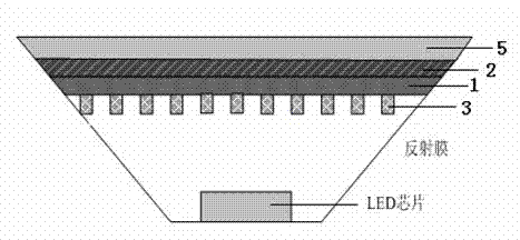
[0022] Please see first figure 1 , figure 1 It is the first embodiment of the optical film with grating in the present invention, and it is also a white light LED composed of the optical film with grating. As shown in the figure, the LED chip is placed in a bowl-shaped support frame with a reflective film around it, and the optical film with a grating of the present invention is placed at the outlet of the bowl, including a substrate 1, which is transparent plastic or glass. The side of the substrate 1 close to the LED light source has a grating 3 , and the other side of the substrate 1 is coated with a fluorescent film 2 . The light-emitting surface of the fluorescent film 2 also has a protective film 5 with some diffusion structures on the protective film.

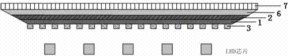
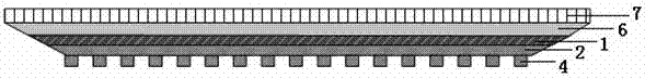
[0023] figure 2 It is the second embodiment of the optical film with grating in the present invention, and it is also a white light illumination backlight system composed of the optical film with grating. As shown i...


PUM


Abstract

The invention provides an optical film with a raster. The optical film comprises a substrate. One side of the substrate close to an LED light source has a raster, and the other side of the substrate is coated with a fluorescent screen, or the side of the substrate close to the LED light source is coated with the fluorescent screen, and one side of the fluorescent screen close to the LED light source has a fluorescence raster. By utilizing diffraction of the raster, part energy of excitation light is converted into waveguide mode transmitted in the fluorescent screen and the optical film formed by the substrate, thus efficiency of converting the excitation light into yellow light is raised, simultaneously the fluorescence raster has a defect line or a micro-cavity, through resonance of the micro-cavity, conversion efficiency of a corresponding wavelength is raised, purity is raised, and a display or illumination requirement is satisfied.

Description

technical field [0001] The invention relates to the technical fields of solid-state lighting and liquid crystal display, in particular to an optical film with a grating. Background technique [0002] White light lighting technology is a new generation of solid-state lighting technology. It has the advantages of high luminous efficiency, mercury-free, long life, and small size. At present, the main methods for realizing white light lighting of LEDs are: (1) three single-color red, green, and blue LEDs to synthesize white light; (2) UV LEDs plus three-color fluorescence; (3) blue LEDs plus yellow fluorescence. The first method uses red, green, blue LED or three primary color chip packages to realize white light, which has the advantages of high color rendering, stable chroma, and adjustable color tone, but the cost of using three LEDs is high, and the LED drive circuit is complicated. The effect of temperature is obvious. The second uses UV to excite three-color fluorescence...

Claims


Application Information

Patent Timeline
Patent Type & Authority Applications(China)
IPC IPC(8): H01L33/50
Inventor 叶志成李潇
Owner 厦门市为纳光电科技有限公司
Why Eureka
Try Eureka