Method for energy-saving charging and discharging of cells and system for testing energy-saving charging and discharging of cells

A charging and discharging and battery technology, which is applied in the field of battery energy-saving charging and discharging testing, can solve the problems of large discharge current ripple coefficient, large volume of power storage devices, and large power grid harmonic pollution.

Active Publication Date: 2012-02-22
DONGGUAN GUANJIA ELECTRONICS EQUIP
View PDF5 Cites 37 Cited by
  • Summary
  • Abstract
  • Description
  • Claims
  • Application Information

AI Technical Summary

Problems solved by technology

[0003]In the existing technology, most of the domestic battery manufacturers still use the original and backward charging and discharging equipment for chemical composition, that is, the charging equipment and the discharging equipment are separated, Charging equipment converts mains electricity into direct current to supply power to batteries. Due to the narrow charging voltage range, it is generally only suitable for several types of batteries; while discharging equipment generally uses resistors as loads to consume the energy of batteries through resistance heating; there is also a A small number of enterprises use the thyristor active inverter discharge device to discharge and send the battery energy back to the grid, but the device has the following defects: 1) It is prone to inverter subversion; 2) The harmonic pollution to the grid is relatively large, and the thyristor The current injected into the grid by the active inverter discharge device is a square wave with large harmonic content; 3) The ripple coefficient of the discharge current is large
[0004] In order to solve the above problems, the Chinese utility model patent No. ZL.200520053515.4 discloses an energy-saving battery charging and discharging system. The way of charging and discharging between the tested bat

Method used


Image

  • Method for energy-saving charging and discharging of cells and system for testing energy-saving charging and discharging of cells
  • Method for energy-saving charging and discharging of cells and system for testing energy-saving charging and discharging of cells
  • Method for energy-saving charging and discharging of cells and system for testing energy-saving charging and discharging of cells

Examples


Embodiment 1

[0059] A battery energy-saving charging and discharging method of the present invention comprises the following steps:

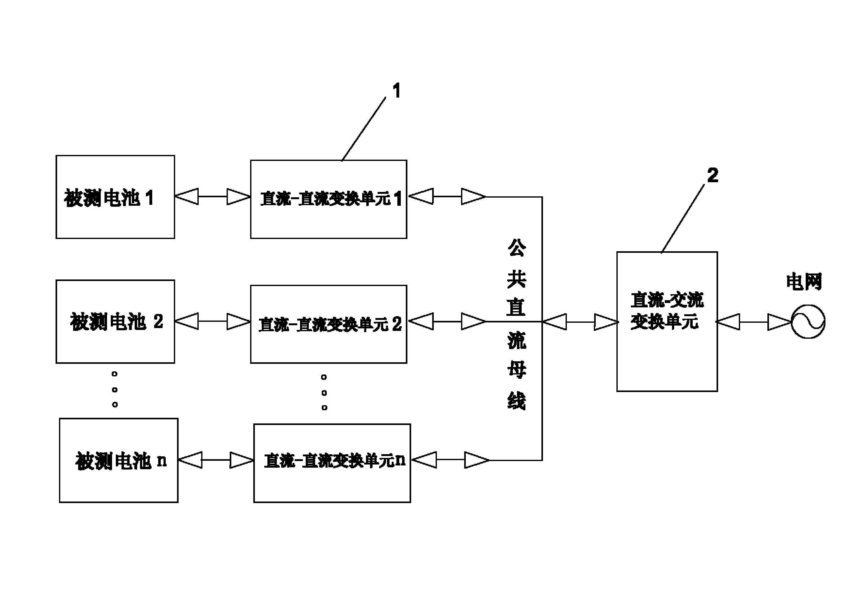
[0060] A. First connect each battery to the corresponding DC-DC conversion unit, each DC-DC conversion unit is connected to one end of the common DC bus, and the other end of the common DC bus is connected to one end of the DC-AC conversion unit, the The other end of the DC-AC conversion unit is connected to the grid;

[0061] B. When the battery is in the discharge state, the battery releases energy to the common DC bus through the DC-DC conversion unit;

[0062] C. When the battery is in the charging state, the battery absorbs the energy of the common DC bus through the DC-DC conversion unit;

[0063] D. When some batteries are in the charging state and some batteries are in the discharging state, the batteries in the discharging state release energy to the common DC bus through the DC-DC conversion unit, and the batteries in the charging state absorb...

Embodiment 2

[0068] A battery energy-saving charging and discharging test system of the present invention is as follows: figure 1 As shown, it includes a battery under test, a DC-DC conversion unit and a DC-AC conversion unit 1, each battery under test is connected to a DC-DC conversion unit 1, and the DC-DC conversion unit 1 is connected to the DC-AC through a common DC bus. The conversion unit 2 is connected, and the DC-AC conversion unit 2 is connected to the power grid.

[0069] There are three working modes of the system:

[0070] 1. When all the batteries under test are in the charging state, the energy from the grid passes through the DC-AC conversion unit 2, the DC-DC conversion unit 1, and the battery under test in sequence, that is, the grid energy charges the battery under test after passing through the test system;

[0071] 2. When all the tested batteries are in the discharge state, the energy from the tested battery passes through the DC-DC conversion unit 1, the DC-AC conv...

Embodiment 3

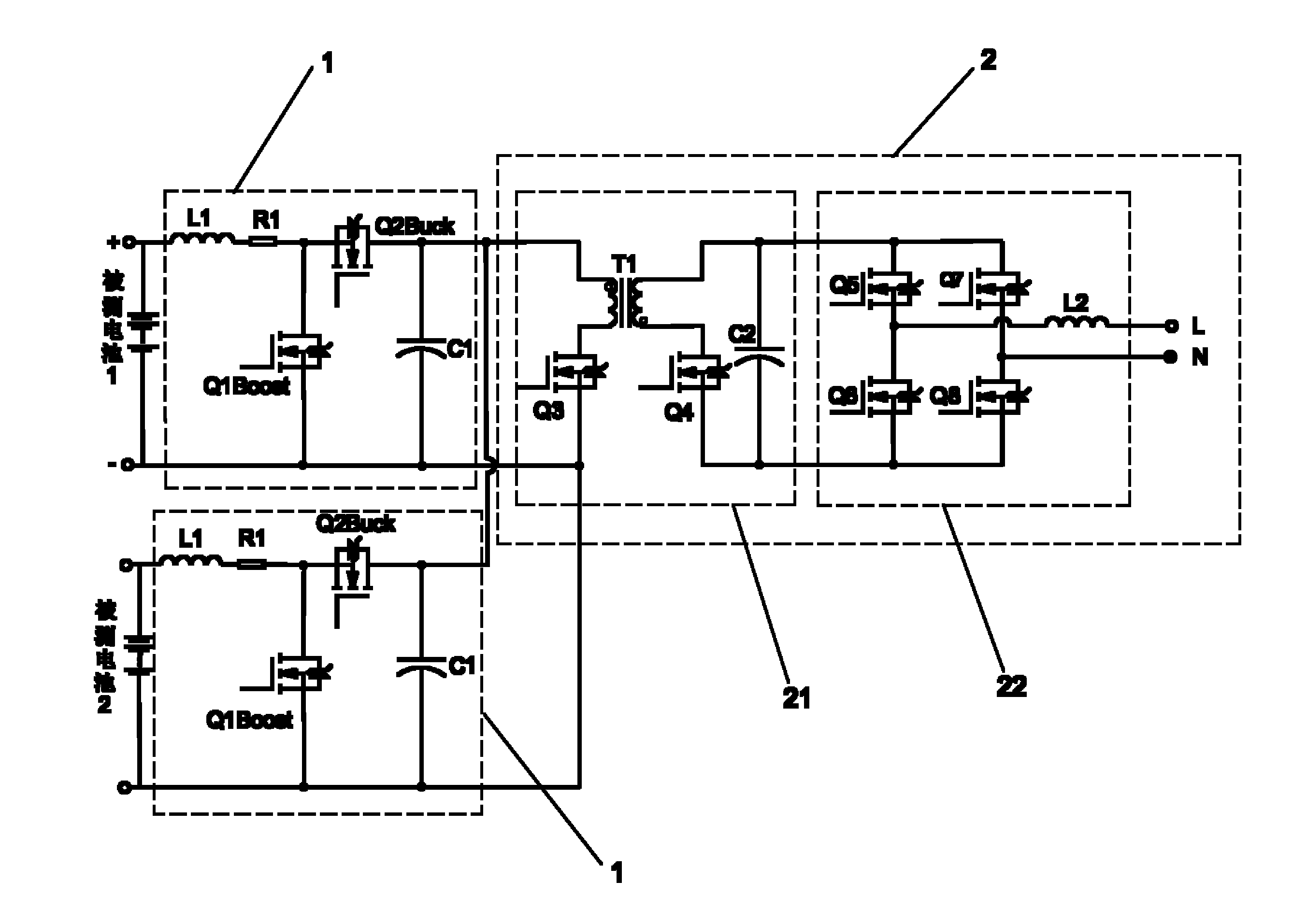
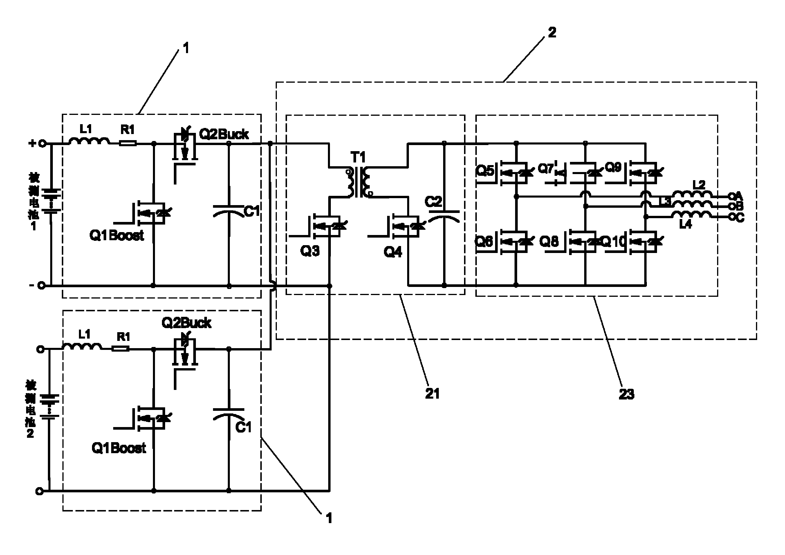
[0076] A battery energy-saving charging and discharging test system of this embodiment is as follows: figure 2 As shown, on the basis of Embodiment 2, the features not explained in this embodiment are explained in Embodiment 2, and will not be repeated here. The difference between this embodiment and embodiment 2 is:

[0077] The DC-DC conversion unit 1 is provided with a BUCK / BOOST bidirectional non-isolated DC-DC conversion circuit, and the BUCK / BOOST bidirectional non-isolated DC-DC conversion circuit includes an inductor L1, a resistor R1, a capacitor C1, and field effect transistors Q1 and Q2 , one end of the inductor L1 is connected to the positive pole of the battery under test, the other end of the inductor L1 is connected to one end of the resistor R1, and the other end of the resistor R1 is connected to the source of the field effect transistor Q2 and the drain of the field effect transistor Q1. The drain of the tube Q2 is connected to one end of the capacitor C1, ...


PUM


Abstract

The invention relates to the technical field of an energy-saving charging and discharging test on cells, and specially, relates to a method for energy-saving charging and discharging of cells and a system for testing energy-saving charging and discharging of cells. When all cells are in a charging state, power is sent from an electrical network and orderly passes through a direct current-alternating current transformation unit, a direct current-direct current transformation unit and the cells. When all the cells are in a discharging state, power is sent from the cells and orderly passes through the direct current-direct current transformation unit, the direct current-alternating current transformation unit and the electrical network. When cell charging powder and cell discharging powder are unequal, the powder unbalance is adjusted by the direct current-alternating current transformation unit and the electrical network. In the invention, charging and discharging of cells are realized simultaneously. Powder produced by cell discharging is fed back to an electrical network so that powder cyclic utilization is realized and powder-saving effects are obtained. A part of the cells are in a charging state and the other part of the cells are in a discharging state so that powder can be transmitted between the two parts without passing through the electrical network and thus powder cyclic utilization efficiency is improved; powder consumption is reduced; charging-discharging integration is realized; and operation processes are simple and efficient.

Description

technical field [0001] The invention relates to the technical field of battery energy-saving charging and discharging tests, in particular to a battery energy-saving charging and discharging method and a testing system. Background technique [0002] Rechargeable batteries (such as lithium batteries, lead-acid batteries, etc.) usually need two steps of formation and capacity separation before leaving the factory. The so-called formation and capacity separation are to make the chemical substances in the internal plate of the battery Fully activate, and judge the capacity of the battery through the charging and discharging process, and carry out screening and classification. The traditional method of formation and capacity division is to charge the battery by connecting it to a charger, and then discharge it by connecting the battery to a resistor, which consumes a lot of energy, especially for large-capacity batteries. [0003] In the existing technology, most of the domestic...

Claims


Application Information

Patent Timeline
IPC IPC(8): H01M10/44H01M10/42G01R31/36
CPCY02E60/10
Inventor 邹曙
Owner DONGGUAN GUANJIA ELECTRONICS EQUIP
Why Eureka
Try Eureka