Leakage protection plug

A leakage protection plug and resistor technology, applied in emergency protection circuit devices, automatic disconnection emergency protection devices, circuits, etc., can solve problems such as electric shock accidents and missing

Inactive Publication Date: 2012-02-29
刘睿刚
View PDF5 Cites 3 Cited by
  • Summary
  • Abstract
  • Description
  • Claims
  • Application Information

AI Technical Summary

Problems solved by technology

[0003] It can be seen from the above that the prerequisite for the existing leakage protection plug to trip when the load end is faulty or the ground wire is accidentally electrified is that there must be a residual current between the load end phase and the neutral wire or there must be an accidental current flow on the load end ground wire. Therefore, the existing leakage protection plug has the following defects: when in use, whether the ground wire of the grounding protection system is missing (for example: the ground wire of the socket is empty, resulting in no grounding) and the load end of the leakage protection plug is insulated by electrical appliances When there is a fault leakage, or when the grounding protection system is abnormal (for example: short circuit of the phase wire and the ground wire) and the ground wire is accidentally electrified, it will cause the exposed metal parts of the electrical appliances to carry dangerous voltages, but they have not formed a loop, so there is no Therefore, although the exposed metal parts of electrical appliances have been charged with dangerous voltage, the existing leakage protection plugs will not automatically trip in this case, only when the human body or livestock touch these When the exposed metal parts have been electrified, a circuit is formed through the human body or livestock, resulting in residual current or ground wire accidental current, which makes the leakage protection plug trip within 0.1S and disconnects the phase wire, neutral wire, and ground wire. Although it can be tripped in time to protect the life safety of people or livestock, in this case, the existing leakage protection plug must first pass through the human body or livestock to generate residual current or ground wire accidental current and flow through the human body or livestock. It can be released to disconnect the phase wire, neutral wire and ground wire, so the existing leakage protection plug will still cause electric shock accidents to human body or livestock.

Method used


Image

  • Leakage protection plug
  • Leakage protection plug
  • Leakage protection plug

Examples


Embodiment 1

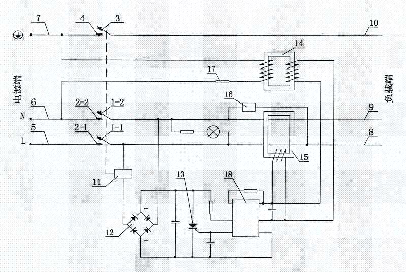
[0027] See figure 1 As shown, a leakage protection plug is mainly composed of the plug shell and the phase, zero, and ground three-pole pins, the phase line 5, the neutral line 6, the ground line 7, the rectifier circuit 12, the thyristor 13, and the zero sequence current transformer of the power terminal. 15. Test circuit 16, weak current detection inductor 14, current-limiting resistance-capacitance element 17, load end phase line 8, neutral line 9, ground line 10, amplifier circuit 18, electromagnetic trip and lock device. The electromagnetic tripping and locking device is mainly composed of the electromagnetic coil 11 and its drive circuit, the phase line contacts 1-1 and 2-1, the neutral line contacts 1-2 and 2-2, the ground line contacts 3 and 4, and the spring , Reset push rod composition. The detection circuit composed of the primary winding of the weak current detection inductor 14 and the current-limiting resistance-capacitance element 17 in series is connected betwee...

Embodiment 2

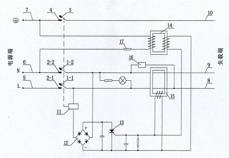
[0034] See figure 2 As shown, compared with embodiment 1, the amplifying circuit 18 described in embodiment 1 is eliminated in this embodiment, and the secondary winding output end of the zero-sequence current transformer 15 is replaced with the amplifying circuit 18 described in embodiment 1. The parallel connection of the input terminal is changed to connect in parallel with the trigger electrode and cathode of the thyristor 13 of this embodiment, and the anode and cathode of the thyristor 13 are respectively connected to the positive and negative electrodes of the output terminal of the rectifier circuit 12, so that the zero sequence current transformer is 15 times The signal output by the secondary winding directly triggers the thyristor 13. Since the signal output by the secondary winding of the zero sequence current transformer 15 is large enough, the thyristor 13 can be triggered without amplification.

[0035] In this embodiment, the current-limiting resistance-capacitanc...

Embodiment 3

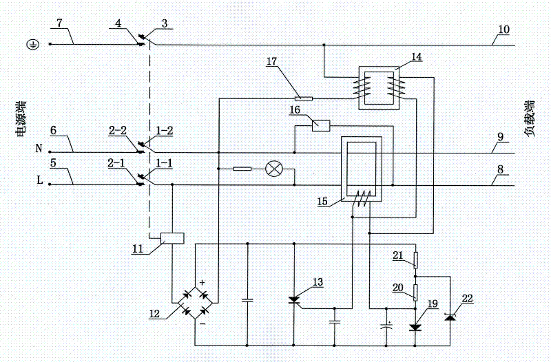
[0039] See image 3 As shown, compared with Embodiment 2, this embodiment adds a clamping diode 19 composed of a combination of a first resistor 21, a second resistor 20, a clamping diode 19, and a Zener diode 22 in the solenoid drive circuit. A positive clamp circuit. The clamp diode 19 is connected in series with the second resistor 20 and the first resistor 21 between the positive and negative terminals of the output terminal of the rectifier circuit 12. One end of the first resistor 21 is connected to the positive terminal of the output terminal of the rectifier circuit 12. The other end of the resistor 21 is connected to one end of the second resistor 20, the other end of the second resistor 20 is connected to the anode of the clamp diode 19, the cathode of the clamp diode 19 is connected to the negative electrode of the output end of the rectifier circuit 12, the other end of the first resistor 21, and the second resistor One end of 20 is also connected to the negative el...


PUM


Abstract

The invention discloses a leakage protection plug, which not only can prevent electrical shock caused by electrical equipment faults, but also can prevent electrical shock caused by accidental electrification of an earth wire. The leakage protection plug is also provided with a weak electric current detection sensor, wherein the weak electric current detection sensor is provided with an iron core, a primary winding and a secondary winding, the primary winding and the secondary winding of the weak electric current detection sensor are both wound on the iron core and are insulatively separated, a detection circuit formed by connecting the primary winding of the weak electric current detection sensor and a flow resistance capacitance resistance element in series is connected between the earth wire and a zero line, and an output end of the primary winding of the weak electric current detection sensor and an output end of a secondary winding of a zero sequence current mutual inductor are respectively connected with an input end of a drive circuit of an electromagnetic coil in parallel.

Description

Technical field [0001] The present invention relates to the technical field of electrical safety protection, in particular to a leakage protection plug. Background technique [0002] Chinese patent document CN1142618C discloses a leakage protection plug with a ground wire that can be opened and closed. The leakage protection plug is not only provided with a zero-sequence current transformer through which the phase wire and the neutral wire pass, but also a ground wire through which the ground wire passes. Line live detection sensor, so it can not only detect whether there is residual current between the phase line and the neutral line at the load end, when the residual current between the phase and the neutral line reaches the preset threshold (for example: 10mA), it can It will trip immediately to cut off the phase, neutral, and ground wires; and when the ground wire is accidentally charged due to an abnormality in the grounding protection system, it can also detect whether ther...

Claims


Application Information

Patent Timeline
Patent Type & Authority Applications(China)
IPC IPC(8): H01R13/66H01R13/70H02H3/32
Inventor 刘睿刚
Owner 刘睿刚
Why Eureka
Try Eureka