Audio high-speed transmission system and method

A high-speed transmission and audio technology, applied in the bus network, data exchange through path configuration, etc., can solve the problems that audio long-distance transmission cannot be widely used in the field of remote monitoring, increased hardware costs, and low cost-effective solutions, and achieves low power consumption. , The effect of small sound quality loss and easy control

Inactive Publication Date: 2012-03-14
DATCENT TECH
View PDF3 Cites 2 Cited by
  • Summary
  • Abstract
  • Description
  • Claims
  • Application Information

AI Technical Summary

Problems solved by technology

[0002] Most of the existing audio long-distance transmission uses a dedicated audio cable. Using a dedicated audio cable, the sound quality is okay if the distance is close, but the sound quality will be poor if the distance is far away, and the noise will come out. Besides, the price of the dedicated audio cable is also expensive. more expensive
Therefore, the existing audio long-distance transmission cannot be widely used in the field of remote monitoring
The digital transmission of audio signals has become a development trend of long-distance transmission. In terms of specific circuit implementation methods, there is another way, which is to use Ethernet physical transmission chips (PHY) to promote network cable transmission, and the sound quality is basically close. But the cost will rise a lot. First of all, the network transmission chip will be much more expensive than the RS485 chip, and the control chip MCU connected to the network transmission chip must have MAC components or be implemented with a programmable logic device FPGA, which will lead to an increase in cost. The cost will increase a lot, and the scheme of using Ethernet physical transmission chip is relatively low cost performance, and the circuit is complicated

Method used


Image

  • Audio high-speed transmission system and method
  • Audio high-speed transmission system and method
  • Audio high-speed transmission system and method

Examples


Embodiment 1

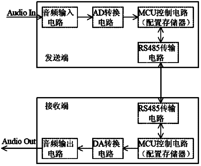
[0044] The audio high-speed transmission system provided by this embodiment is connected as figure 1 As shown, it includes the sending end and the receiving end. The sending end is composed of audio input circuit, AD conversion circuit, sending end MCU control circuit and sending end RS485 transmission circuit. The receiving end is composed of receiving end RS485 transmission circuit, receiving end MCU control circuit, DA A conversion circuit and an audio output circuit; the audio input circuit includes an audio input interface and a resistance-capacitance impedance matching circuit. The audio input interface is used to access analog audio signals. The audio input circuit is connected to the AD conversion circuit through the resistance-capacitance impedance matching circuit. Connection; AD conversion circuit is used to convert analog audio signals into digital audio signals, AD conversion circuit is equipped with a standard I 2 S interface; the sending end MCU control circuit has...


PUM


Abstract

The invention relates to an audio high-speed transmission system and method. The audio high-speed transmission system comprises a transmitter and a receiver, wherein the transmitter consists of an audio input circuit, an AD (Analogue-to-Digital) conversion circuit, a transmitter MCU (Microprogrammed Control Unit) control circuit and a receiver RS485 (Remote Sensing485) transmission circuit; and the receiver consists of a receiver RS485 transmission circuit, a receiver MCU control circuit, a DA (Digital-to-Analogue) conversion circuit and an audio output circuit. The audio high-speed transmission system is used for transmitting an audio to the other end in high quality through an ordinary cable; and the cost is low and the high-quality transmission is convenient to control. As RS485 transmission is digital transmission, no sound quality is lost in the process of transmission. Minor sound quality loss is generated by digitalizing an analogue signal, but the sound quality loss is very small when the sampling rate and the resolution ratio reach to certain degrees. The digitalization of an audio signal is advantaged in convenience for signal processing, storage and transmission.

Description

technical field [0001] The invention relates to an audio transmission system and method. Background technique [0002] Most of the existing audio long-distance transmission uses a dedicated audio cable. Using a dedicated audio cable, the sound quality is okay if the distance is close, but the sound quality will be poor if the distance is far away, and the noise will come out. Besides, the price of the dedicated audio cable is also expensive. more expensive. Therefore, the existing audio long-distance transmission cannot be widely used in the field of remote monitoring. The digital transmission of audio signals has become a development trend of long-distance transmission. In terms of specific circuit implementation methods, there is another way, which is to use Ethernet physical transmission chips (PHY) to promote network cable transmission, and the sound quality is basically close. But the cost will rise a lot. First of all, the network transmission chip will be much more ...

Claims


Application Information

Patent Timeline
Patent Type & Authority Applications(China)
IPC IPC(8): H04L12/40
Inventor 吕海军吕兵仲健
Owner DATCENT TECH
Why Eureka
Try Eureka