Static CT (computed tomography) scanner system and scanning method thereof

A scanner and static technology, applied in the field of CT scanners, can solve the problems of increasing the complexity of the X-ray source, slow startup speed, and the inability to turn off the electron source, etc., to achieve the effect of solving motion artifacts, easy maintenance, and simple structure

Inactive Publication Date: 2012-03-21
SUZHOU INST OF BIOMEDICAL ENG & TECH
View PDF4 Cites 22 Cited by
  • Summary
  • Abstract
  • Description
  • Claims
  • Application Information

AI Technical Summary

Problems solved by technology

The mode of thermal emission generating electrons leads to its slow start-up
When a pulsed synchronous scan (such as a scan of a specific phase of the heart rhythm) is required, it cannot turn off the electron source, but can only adjust the bias voltage to suppress the electrons from hitting the anode target, or set a mechanical gate at the ray exit, thereby increasing Sophistication of X-ray sources

Method used


Image

  • Static CT (computed tomography) scanner system and scanning method thereof
  • Static CT (computed tomography) scanner system and scanning method thereof
  • Static CT (computed tomography) scanner system and scanning method thereof

Examples


Embodiment 1

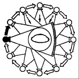
[0039] See Figure 4 and Figure 5 As shown, a static CT scanner system includes a power system 1, an X-ray source system 2, a detector system 3, a data acquisition system 4, and a computer 5. The detector system 3 is used to receive the X-ray source system 2 The X-ray beam emitted, the data acquisition system 4 is connected to the detector system 3, the computer 5 is connected to the data acquisition system 4, and the power system 1 is respectively connected to the X-ray source system 2 and the detector The system 3 and the data acquisition system 4 are used to provide the required high voltage and common power. The X-ray source system 2 includes several carbon nanotube-based X-ray source modules 201, and the several X-ray source modules 201 are uniform Distributed on a circular track 6, and a collimator 7 is correspondingly provided under each X-ray source module 201; the detector system 3 includes a plurality of detector modules 301, and the detection of the plurality of dete...

Embodiment 2

[0044] A scanning method of a static CT scanner system. First, open one X-ray source module; then, turn on the other X-ray source modules one by one in a clockwise or counterclockwise direction.

Embodiment 3

[0046] A scanning method for a static CT scanner system. First, open at least two X-ray source modules, while ensuring that the coverage areas of the X-ray beams emitted by the opened X-ray source modules on the detector system do not overlap each other; then, Open the other X-ray source modules in the clockwise or counterclockwise direction at the same time according to the positions determined by the above-mentioned X-ray source modules.


PUM


Abstract

A static CT (computed tomography) scanner system comprises a power system, an X-ray source system, a detector system, a data acquisition system and a computer. The detector system is used for receiving X-ray beams emitted by the X-ray source system, the data acquisition system is connected with the detector system, the computer is connected with the data acquisition system, the power system is respectively connected with the X-ray source system, the detector system and the data acquisition system, the X-ray source system comprises a plurality of X-ray source modules based on carbon nanotubes, the X-ray source modules are evenly distributed on an annular rail, a collimator is disposed below each X-ray source module correspondingly, the detector system comprises a plurality of detector modules, the detection faces of the detector modules form a ring and are parallel to the annular rail, and the X-ray source system is capable of projecting emitted X-ray beams to the detection faces of the detector system through slits among the collimators. The static CT scanner system is simple in structure and short in run-down time.

Description

[0001] Technical field [0002] The invention belongs to the field of CT scanners. [0003] Background technique [0004] CT is widely used in clinical practice. In order to realize tomographic imaging, there are two schemes of CT currently in use. The first scheme is that the CT tube rotates around the human body to obtain projection images of the imaging object at different perspectives (see figure 1 ); The second solution is to use a large-scale special scanning electron beam X-ray tube, through the deflection coil to control the position of the electron beam bombardment of the target, and then obtain projection images of different perspectives (see figure 2 ). [0005] No matter the first scheme or the second scheme, the principle of X-ray generation is basically the same. Heating the filament, when the filament temperature reaches thousands of degrees Celsius, thermionic electrons are emitted, and the thermionic electrons are accelerated and hit the anode under the action of t...

Claims


Application Information

Patent Timeline
IPC IPC(8): A61B6/03
Inventor 邢晓曼代秋声
Owner SUZHOU INST OF BIOMEDICAL ENG & TECH
Why Eureka
Try Eureka