Deep-hole drilling jig

A technology of deep hole drilling and drilling dies, which is applied to the drilling dies for workpieces, etc., can solve the problems of long drilling time, difficult chip removal, stuck twist drills, etc., so as to reduce processing costs, high drilling efficiency, The effect of easy chip evacuation

Inactive Publication Date: 2012-03-28
CRRC LUOYANG CO LTD
View PDF0 Cites 5 Cited by
  • Summary
  • Abstract
  • Description
  • Claims
  • Application Information

AI Technical Summary

Problems solved by technology

When drilling a deep hole with an extended twist drill, put the workpiece on the drilling machine, start the drilling machine, shake the handle to make the extended twist drill bit feed downwards, and drill through the hole of the workpiece. There are the following defects: 1. The purchase cost of the extended twist drill is high , an extended twist drill costs 500-1000 yuan; 2. Difficult chip removal, frequent chip removal, low efficiency, and long drilling time; 3. Incomplete chip removal, iron filings are easy to get stuck on the extended twist drill, making the twist drill It is difficult to take out the broken twist drill in the hole of the workpiece, and the workpiece can only be scrapped, and the use cost is high
When drilling a deep hole with a gun drill, put the workpiece on the drilling machine, start the rotary table of the drilling machine, drive the workpiece to rotate with the center line of the deep hole as the center, shake the handle to make the gun drill go down to drill the hole, and at the same time, go through the center hole of the gun drill to Cooling liquid is added to the processing surface to perform forced cooling and forced chip removal until the hole is drilled. There are the following defects: 1. The cost is high, and a gun drill costs 4-5 thousand yuan; 2. When drilling with a gun drill, The gun drill does not rotate, the workpiece rotates, most of the equipment cannot be used, and a special machine must be used, and the equipment has great limitations

Method used


Image

  • Deep-hole drilling jig
  • Deep-hole drilling jig

Examples


Embodiment Construction

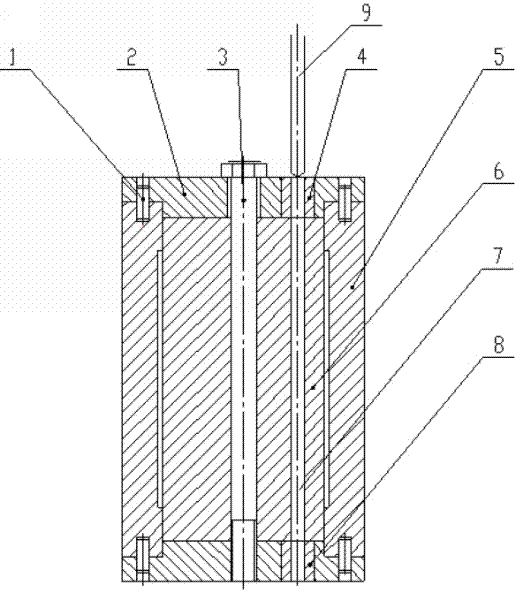
[0011] As shown in the accompanying drawings, the present invention is made up of four alignment pins 1, two drill templates 2, a compression screw 3, drill sleeve one 4, drill sleeve two 8, and drill template body 5. The two drill templates 2 are respectively inlaid with a drill sleeve 1 4 and a drill sleeve 2 8. The drill template 2 is positioned together with the drill template body 5 through four positioning pins 1. The workpiece 6 is installed in the drill template body 5. Between the templates 2, use the compression screw rod 3 to compress, and the first drill sleeve 4 is concentric with the second drill sleeve 8.

[0012] When drilling, the workpiece 6 is put into the template body 5, the template body 5 is clamped with two templates 2, four positioning pins 1 are inserted, the compression screw 3 is tightened, the template is placed on the drill press, Drill bushing 1 4 faces up, start the drilling machine, shake the handle to make the twist drill bit 9 feed downwards,...


PUM


Abstract

The invention discloses a deep-hole drilling jig for processing deep holes. Two drilling jig plates and a drilling jig body are positioned by positioning pins; a workpiece is arranged in the drilling jig body and between the two drilling jig plates and is pressed by a pressing screw; and the two drilling jig plates are internally and respectively provided with a drilling sleeve I and a drilling sleeve II which are concentric. The deep-hole drilling jig adopts a method of oppositely drilling at two ends to process the deep holes, and since holes concentrically drilled by the two drilling sleeves are not easy to deviate, are high in concentricity are not subjected to limitation of equipment, and the processing of the deep holes can be realized on any drilling machine; the drilling jig can be designed and manufactured according to the shape of the workpiece, and is simple in structure and low in cost; and a lengthened twist drill can not be adopted, chip removal is easy, the fracture of a drilling bit is effectively prevented, the processing cost is reduced and the hole drilling efficiency is high.

Description

technical field [0001] The invention relates to the technical field of mechanical processing, in particular to a deep hole drilling mold for drilling deep holes. Background technique [0002] At present, extended twist drills and gun drills are usually used to drill deep holes in workpieces. When drilling a deep hole with an extended twist drill, put the workpiece on the drilling machine, start the drilling machine, shake the handle to make the extended twist drill bit feed downwards, and drill through the hole of the workpiece. There are the following defects: 1. The purchase cost of the extended twist drill is high , an extended twist drill costs 500-1000 yuan; 2. Difficult chip removal, frequent chip removal, low efficiency, and long drilling time; It is difficult to take out the twist drill broken in the hole of the workpiece, and the workpiece can only be scrapped, and the use cost is high. When drilling a deep hole with a gun drill, put the workpiece on the drilling ...

Claims


Application Information

Patent Timeline
IPC IPC(8): B23B47/28
Inventor 邹家龙李光杰李冬平
Owner CRRC LUOYANG CO LTD
Why Eureka
Try Eureka