
Millimeter wave linearly polarized vehicle-mounted fanned beam antenna

A fan-shaped beam and linear polarization technology, applied in antennas, slot antennas, antenna arrays, etc., can solve the problems of difficult processing, narrow working bandwidth, and low radiation efficiency, and achieve short processing cycle, wide working bandwidth and small size Effect

Inactive Publication Date: 2013-12-25
BEIJING INSTITUTE OF TECHNOLOGYGY
View PDF3 Cites 0 Cited by
  • Summary
  • Abstract
  • Description
  • Claims
  • Application Information

AI Technical Summary

Problems solved by technology

The traditional metal waveguide slot antenna array generally adopts the form of wide-side standing wave slot array, but it has the disadvantages of difficult processing, low yield, high processing cost, and narrow working bandwidth.
The microstrip patch array antenna is also an array antenna form with the advantages of planar type, easy integration, and small size, but its radiation efficiency is low, resulting in low gain

Method used


Image

  • Millimeter wave linearly polarized vehicle-mounted fanned beam antenna
  • Millimeter wave linearly polarized vehicle-mounted fanned beam antenna
  • Millimeter wave linearly polarized vehicle-mounted fanned beam antenna

Examples


Embodiment Construction

[0029] In order to better illustrate the purpose and advantages of the present invention, the present invention will be further described in detail below in conjunction with the accompanying drawings and embodiments.

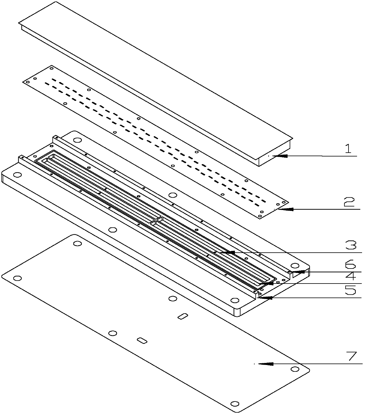
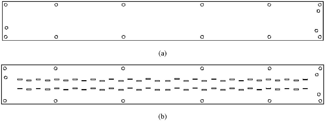
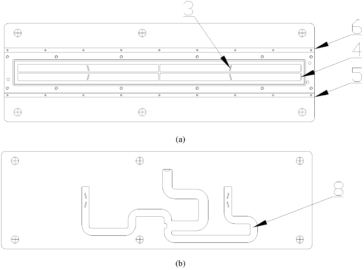
[0030] As a preferred embodiment of the present invention, the structure of the millimeter-wave linearly polarized vehicle-mounted sector beam antenna is as follows: figure 1 and image 3 (b) shown. The array antenna includes a rigid support foam 1, a microstrip slot surface 2, a coupling feeding slant 3, a waveguide slot 4, a metal wall (including a left metal wall 5 and a right metal wall 6), a metal plate 7, and a plane and Poor network8.

[0031] Taking the signal receiving process as the sequence, the structure of the array antenna is as follows: the rigid support foam 1 is placed directly above the microstrip slot surface 2 to protect the microstrip slot surface 2 and ensure its flatness; the two sides of the rigid support foam 1 The sides are respectiv...


PUM


Abstract

The invention discloses a millimeter wave linearly polarized vehicle-mounted fanned beam antenna, belonging to the technical field of antennas. The antenna comprises a planar sum-difference network, coupled-fed slots, waveguide slots, metal walls, a microstrip slot surface, rigid support foam and a metal sheet, wherein a sum port and a difference port of the planar sum-difference network are ports connected with the outside; the waveguide slots are formed on the back of the planar sum-difference network; the waveguide slots and the planar sum-difference network are connected by the coupled-fed slots; the metal walls are positioned at the two sides of the waveguide slots; the planar sum-difference network, the coupled-fed slots, the waveguide slots and the metal walls integrally serve as an antenna back sheet; the metal sheet is positioned on the reverse side of the antenna back sheet and covers the planar sum-difference network; the microstrip slot surface is bonded with the waveguide slots by conductive adhesives; and the rigid support foam is positioned between the metal walls, is fixed on the metal walls and covers the microstrip slot surface. The antenna has the following beneficial effects: the defects of high processing cost, low yield, small work bandwidth and long processing period of metal waveguide slot arrays and the defect of low gain of microstrip patch array antennas are overcome.

Description

technical field [0001] The invention relates to a millimeter-wave linearly polarized vehicle-mounted fan-shaped beam antenna, which belongs to the technical field of antennas. Background technique [0002] With the rapid development of mobile satellite communication technology and car navigation systems, vehicle-mounted smart antenna systems have been used more and more. A good-performance vehicle-mounted smart antenna communication and positioning system has high requirements for antenna performance. [0003] The metal waveguide slot antenna is an antenna that is easy to achieve narrow beam, high gain, and low sidelobe. It has the advantages of low profile, easy integration, and small size. antenna. The traditional metal waveguide slot antenna array generally adopts the form of a wide-side standing wave slot array, but it has the disadvantages of difficult processing, low yield, high processing cost, and narrow working bandwidth. The microstrip patch array antenna is also...

Claims


Application Information

Patent Timeline
Patent Type & Authority Patents(China)
IPC IPC(8): H01Q13/10H01Q21/00H01Q25/02H01Q1/32
Inventor 刘埇闫丕贤吕昕倪鸿宾孙厚军
Owner BEIJING INSTITUTE OF TECHNOLOGYGY
Learn More