Sea bottom natural gas hydrate gas lift mining method and device

A mining method and hydrate technology, which is applied in the fields of mining fluids, wellbore/well valve devices, earthwork drilling, etc., can solve the problems of small heating area, unstable fluid production, large energy consumption, etc., and achieve stable working conditions , Low operating cost and small demand

Inactive Publication Date: 2012-04-04
CHANGZHOU UNIV
View PDF5 Cites 23 Cited by
  • Summary
  • Abstract
  • Description
  • Claims
  • Application Information

AI Technical Summary

Problems solved by technology

The hydraulic lifting method is to use the subsea relay pump to elevate the multiphase mixed and flowing hydrate, and then use hot water to decompose the hydrate. This method needs to input current into the seabed to drive the transfer pump, which consumes a lot of energy and affects the insulation of the cable connector. High requirements, complex structure of subsea equipment, many moving parts, unstable fluid production, and low equipment reliability
The Chinese patent application number is 200910235236.2, and the name is "a seabed natural gas hydrate mining method". The thermal stimulation mining method is adopted. The main object of this method is natural gas hydrate in the seabed rock formation. Two wells need to be drilled, and the cost is high and the process flow is high. Complicated, poor economy, low heat utilization efficiency, small heating area
[0003] To sum up, the existing gas hydrate exploitation methods and equipment do not take into account the characteristics of low abundance, wide distribution area and thin distribution thickness of natural gas hydrate. The collection of hydrates to the sea surface is not considered
During mining, it is necessary to build a subsea transfer station, lower microwave generators or drill branch wells, and the process is complex

Method used


Image

  • Sea bottom natural gas hydrate gas lift mining method and device
  • Sea bottom natural gas hydrate gas lift mining method and device
  • Sea bottom natural gas hydrate gas lift mining method and device

Examples


Embodiment Construction

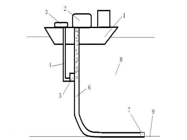
[0017] see figure 1 , install a natural gas separation and storage system 2 and an injected gas storage and pressurization system 3 on the offshore gas production platform or ship 1 . The gas pressurization system in the storage and pressurization system 3 may be a centrifugal pump, or may be other types of explosion-proof gas compression pumps. The natural gas separation and storage system 2 is connected to the outlet of the gas production pipeline 6 . The gas production pipeline 6 extends downward into the seawater 8. The lower opening of the gas production pipeline 6 is the gas production pipeline inlet 7, and the gas production pipeline 6 extends into the seabed natural gas hydrate and sediment mixed layer 9 through the gas production pipeline inlet 7. The gas production pipeline 6 is a channel for the subsea natural gas hydrate, water and sediment mixture to flow to the sea surface. Several metal or non-metallic or composite pipelines are connected by couplings. Coiled t...


PUM


Abstract

The invention discloses a sea bottom natural gas hydrate gas lift mining method and a sea bottom natural gas hydrate gas lift mining device. Gas is injected into a gas injection pipeline from a sea surface, so that resultant force of force applied to a diaphragm by the injected gas and force applied to a valve ball by liquid in a gas recovery pipeline is greater than elastic force of a spring, a valve rod drives the valve ball to leave a valve seat, the injected gas is injected into the gas recovery pipeline, and the density of the liquid in the gas recovery pipeline is reduced; and the gas recovery pipeline forms sucked water flow at the inlet of the gas recovery pipeline by using a difference of pressure outside and inside the pipeline, and natural gas hydrate particles in a sea bottom natural gas hydrate and silt mixed layer are sucked and flow into a separation and storage system on a sea surface gas recovery platform or a ship, so that sea bottom natural gas hydrates are continuously mined, the required quantity of the injected gas is small, operating cost is low, the method and the device are suitable for mining low-abundance natural gas hydrates dispersed on a sea bed, and the environment is not influenced. The device has a simple structure and a stable working state.

Description

technical field [0001] The present invention relates to a method and a production device for exploiting submarine natural gas hydrate by injecting gas from the sea into a gas production pipeline. Background technique [0002] The reserves of submarine natural gas hydrates are huge. The traditional natural gas hydrate mining technologies mainly include solid mining methods, hydraulic lifting methods, thermal excitation mining methods, and microwave mining methods. For example: the solid mining method disclosed in the Chinese Patent No. 200710168759.0 and titled “A Subsea Gas Hydrate Extraction Method and Device”, uses a submarine hose to inhale the solid form of natural gas hydrate, and transports the mud to the sea surface through a submarine transfer station , and then use high temperature seawater to decompose the collected natural gas hydrate. The hydraulic lifting method is to use a subsea transfer pump to lift the multiphase mixed flow hydrate, and then use hot water t...

Claims


Application Information

Patent Timeline
Patent Type & Authority Applications(China)
IPC IPC(8): E21B43/01E21B43/16E21B34/08
CPCE21B2043/0115E21B41/0099
Inventor 何岩峰于晓玲李涛吴艳华
Owner CHANGZHOU UNIV
Why Eureka
Try Eureka