Time domain analysis method for transient response of lossy nonuniform multi-conductor transmission lines

A multi-conductor transmission line and transient response technology, applied in special data processing applications, instruments, electrical digital data processing, etc., can solve problems affecting the accuracy of transient response analysis, unable to analyze transmission lines, and divergence of analysis results

Inactive Publication Date: 2013-06-26
XIDIAN UNIV
View PDF1 Cites 0 Cited by
  • Summary
  • Abstract
  • Description
  • Claims
  • Application Information

AI Technical Summary

Problems solved by technology

However, the calculation results oscillate due to the use of the central difference method. This oscillation problem may affect the accuracy of the transient response analysis, resulting in wrong transient analysis results. In severe cases, the analysis results may even diverge, and the transient response of the transmission line cannot be analyzed. to analyze

Method used


Image

  • Time domain analysis method for transient response of lossy nonuniform multi-conductor transmission lines
  • Time domain analysis method for transient response of lossy nonuniform multi-conductor transmission lines
  • Time domain analysis method for transient response of lossy nonuniform multi-conductor transmission lines

Examples


Embodiment 1

[0059] The software MATLAB is used for simulation, and a simulated excitation voltage source is added to the attack line in the lossy non-uniform multi-conductor transmission line. For the signal waveform of the excitation source, see Figure 4 .

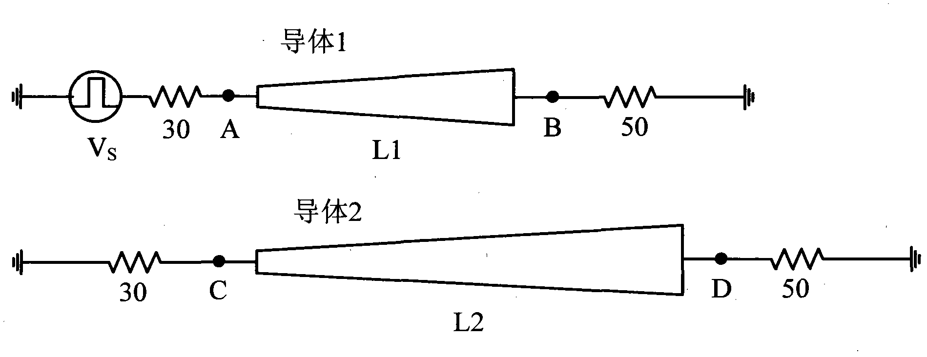
[0060] The total number of lossy non-uniform multi-conductor transmission lines analyzed should be greater than or equal to 3, of which at least one is an infinitely large metal plate transmission line as a reference conductor, and there are two transmission lines as signal lines that couple and interfere with each other, see image 3 , image 3 It is a simulation model of a unequal-length non-uniform lossy conductor transmission line terminated with a resistive load, in which conductor 1 and conductor 2 are two transmission lines that couple and interfere with each other as signal lines, but image 3 An infinitely large metal plate transmission line as a reference conductor is not shown in . The transmission line that adds the ex...

Embodiment 2

[0076] The time-domain analysis method of the transient response of the lossy non-uniform multi-conductor transmission line is the same as that in Example 1, using such as image 3 The simulation model shown is a 3-conductor lossy non-uniform transmission line terminated with a resistive load. In the figure, conductors 1 and 2 are both signal lines, and conductor 3 is not shown in the figure. Conductor 3 is an infinite metal plate as a reference conductor. L1 and L2 are the lengths of conductor 1 and conductor 2, respectively. Terminals A, B, C and D represent the terminals on both ends of conductors 1 and 2, respectively. The distribution parameters of the transmission line are:

[0077] L = L ( z ) Lm ( z ...

Embodiment 3

[0106] The time-domain analysis method of the transient response of the lossy non-uniform multi-conductor transmission line is the same as that of Example 1-2, and the simulation model and conditions are also the same as those of Example 1-2. image 3 The lengths of conductor 1 and conductor 2 in the simulation model are 0.1m and 0.2m respectively. The voltage transient response waveforms of the transmission line terminals A and B obtained by using the FDTD method are as follows: Figure 9 As shown, the voltage transient response waveforms of transmission line terminals C and D are as follows Figure 10 shown. Under the same simulation conditions, the voltage transient response waveforms of the transmission line terminals A and B obtained by using the time domain analysis method proposed in the present invention are as follows: Figure 11 As shown, the voltage transient response waveforms of transmission line terminals C and D are as follows Figure 12 shown. Observed Fig...


PUM


Abstract

The invention provides a time domain analysis method for a transient response of lossy nonuinform multi-conductor transmission lines and aims to solve the problem that the coupling among the lossy nonuniform multi-conductor transmission lines interferes with the computation in the field of integrity of electronic circuit signals. The method comprises the following steps of: performing differential dispersion on space differential operators in an electric wave equation; and integrating time differential operators in the electrical wave equation by a trapezoidal integration method to ensure that the oscillation, which is caused by a central difference method, of a computed result can be eliminated effectively, voltage and current transient response waveforms of any point on the transmissionlines can be acquired; and the transient analysis of the transmission lines in a longer time period is effective, the waveforms can be analyzed in a longer duration without large errors, and the coupled transmission lines are not needed to be decoupled when a model of the transmission lines is built. By the method, the computational load is reduced, and the simulation efficiency is improved. The method can be used for analyzing the transient response of the lossy nonuinform multi-conductor transmission lines.

Description

technical field [0001] The invention belongs to the field of signal integrity of electronic circuits, and relates to electromagnetic compatibility of high-speed circuits, in particular to coupling interference between transmission lines, in particular to a lossy non-uniform multi-conductor transmission line transient response time domain analysis method, which can be used to analyze lossy non-uniform multi-conductor transmission lines. The transient response of non-uniform multi-conductor transmission lines provides theoretical guidance for reducing interconnect effects in circuits, thereby ensuring the signal integrity of circuits. Background technique [0002] As VLSI feature size decreases, rise time decreases, integration scale increases, and clock frequency increases, interconnect effects such as delay, reflection, distortion, and crosstalk caused by interconnect lines can affect circuit performance metrics , makes the system unstable, and even affects the normal operat...

Claims


Application Information

Patent Timeline
Patent Type & Authority Patents(China)
IPC IPC(8): G06F17/50
Inventor 叶强史凌峰曹成美来新泉贾军
Owner XIDIAN UNIV
Why Eureka
Try Eureka