Method for manufacturing negative electrode of lithium titanate battery

A technology of lithium titanate battery and manufacturing method, which is applied to battery electrodes, circuits, electrical components, etc., can solve the influence of characteristic performance of lithium titanate battery, poor electrical conductivity of lithium titanate material, poor affinity between material and current collector, etc. problems, to achieve the effect of promoting the comprehensive performance of the electrode, improving the bonding effect, and improving the high-rate and fast charging and discharging performance.

Inactive Publication Date: 2012-04-18
NANJING SHUANGDENG SCI TECH DEV RES INST
View PDF3 Cites 13 Cited by
  • Summary
  • Abstract
  • Description
  • Claims
  • Application Information

AI Technical Summary

Problems solved by technology

[0003] However, in the actual production and application process, the bonding effect of the negative electrode material of lithium titanate battery is not good, the powder shedding phenomenon of the electrode is serious, the affinity between the material and the current collector is poor, and the conductivity of the lithium titanate material itself is poor, and the inherent electrons of the material Conductivity is only 10 -9 S / cm, according to the existing lithium battery negative electrode production method, the active slurry is directly coated on the current collector, which seriously affects the characteristic performance of lithium titanate battery, especially the performance of high-rate rapid charge and discharge

Method used


Image

  • Method for manufacturing negative electrode of lithium titanate battery

Examples


Embodiment 1

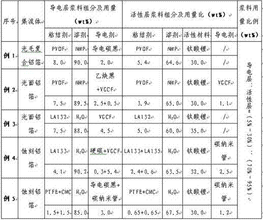
[0011] According to Example 1 in the attached table, after mixing PVDF and NMP evenly, add conductive carbon black, and stir well to make a conductive layer slurry; then mix PVDF and NMP well, add lithium titanate material, and stir well to make an active layer slurry. Layer slurry; evenly coat the conductive layer slurry on the surface of the smooth wool composite aluminum foil, and when the surface is slightly dry without obvious fluid, apply the active layer slurry on it, and control the density of both sides at 150-240g / m 2 , dry it.

Embodiment 2

[0013] According to Example 2 in the attached table, after mixing PVDF and NMP evenly, add acetylene black and VGCF, and stir thoroughly to make a conductive layer slurry; then mix PVDF and NMP evenly, add pre-mixed VGCF and lithium titanate to mix Material, fully stir to make the active layer slurry; evenly coat the conductive layer slurry on the surface of the smooth aluminum foil, when the surface is slightly dry and no obvious fluid, apply the active layer slurry on it, the double-sided surface density Controlled at 150~240g / m 2 , dry it.

Embodiment 3

[0015] According to example 3 in the attached table, LA132 and H 2 After O is mixed evenly, add VGCF and fully stir to make a conductive layer slurry; then LA132 and H 2 O After fully mixing evenly, add lithium titanate material and stir well to make active layer slurry; evenly coat the conductive layer slurry on the surface of smooth aluminum foil, and when the surface is slightly dry without obvious fluid, apply the active layer slurry Coated on it, the double-sided density is controlled at 150-240g / m 2 , dry it.


PUM

PropertyMeasurementUnit
electrical conductivityaaaaaaaaaa

Abstract

The invention provides a method for manufacturing a negative electrode of a lithium titanate battery, which comprises the following steps of: firstly coating a conductive layer sizing agent on a current collector, then coating an active layer sizing agent mainly made of lithium titanate, and improving and optimizing components and proportioning of the conductive layer sizing agent and the active layer sizing agent. The method is used for manufacturing the negative electrode of the lithium titanate battery and has the advantages that the bonding effect of the material of the negative electrode of the battery and the current collector is obviously improved, the powder falling phenomenon is effectively reduced, the conductivity performance of the electrode is improved, the combination property of the electrode is promoted to exert, and the electrochemistry performance of the manufactured lithium titanate battery is increased.

Description

technical field [0001] The invention belongs to the technical field of lithium ion batteries, and in particular relates to a method for manufacturing a negative electrode of a lithium titanate battery. Background technique [0002] Lithium titanate is a composite oxide composed of metal lithium and low-potential transition metal titanium. As a negative electrode active material for lithium-ion batteries, its biggest feature is "zero strain". The so-called "zero strain" means that the lattice constant and volume change of the lithium titanate crystal are very small (<1%) when inserting and extracting lithium ions. In the charge and discharge cycle, this "zero strain" can avoid the structural damage caused by the back and forth expansion and contraction of the electrode material, thereby improving the cycle performance and service life of the electrode, reducing the battery specific capacity fading caused by the cycle, and has a very good performance. Resistance to overcha...

Claims


Application Information

Patent Timeline
Patent Type & Authority Applications(China)
IPC IPC(8): H01M4/1391
CPCY02E60/122Y02E60/10
Inventor 陈冰花丁同臣杨宝峰曹殿学莫英华胡华冲
Owner NANJING SHUANGDENG SCI TECH DEV RES INST
Why Eureka
Try Eureka