
Anti-blockage raw coal cabin

The technology of raw coal bunker and bunker wall is applied in the field of raw coal bunker with anti-blocking function, which can solve the problems of coal cut off, poor coal feeding, and failure of the pulverizing system to work normally, and achieve the effect of eliminating blockage and good vibration effect.

Inactive Publication Date: 2012-04-25
WISDRI ENG & RES INC LTD
View PDF5 Cites 0 Cited by
  • Summary
  • Abstract
  • Description
  • Claims
  • Application Information

AI Technical Summary

Problems solved by technology

The silo with a symmetrical structure, when the material is stored in the silo to a certain amount during the falling process, due to the pressure of the silo, the viscosity between the raw coal, and the balance force of accumulation, the lower part of the raw coal silo is prone to Phenomena such as hardening and arching will cause poor coal feeding, and in severe cases, it will cause coal breakage, cause the system to shut down, and make the pulverizing system unable to work normally
Due to the spontaneous combustion characteristics of coal, coal blocking can easily cause safety hazards
If the moisture content of the coal increases, the amount of pulverized coal increases, and the coal becomes cohesive, coal blockage is more likely to occur, resulting in having to stop production and clean it manually, which not only affects the system operation rate, but also increases the labor intensity of the workers.
In response to the above problems, some people have proposed some solutions, most of which are solved by adding a dredging device in the raw coal bunker, which has a single effect and does not prevent blockage by changing the shape and structure of the raw coal bunker

Method used


Image

  • Anti-blockage raw coal cabin
  • Anti-blockage raw coal cabin

Examples


Embodiment Construction

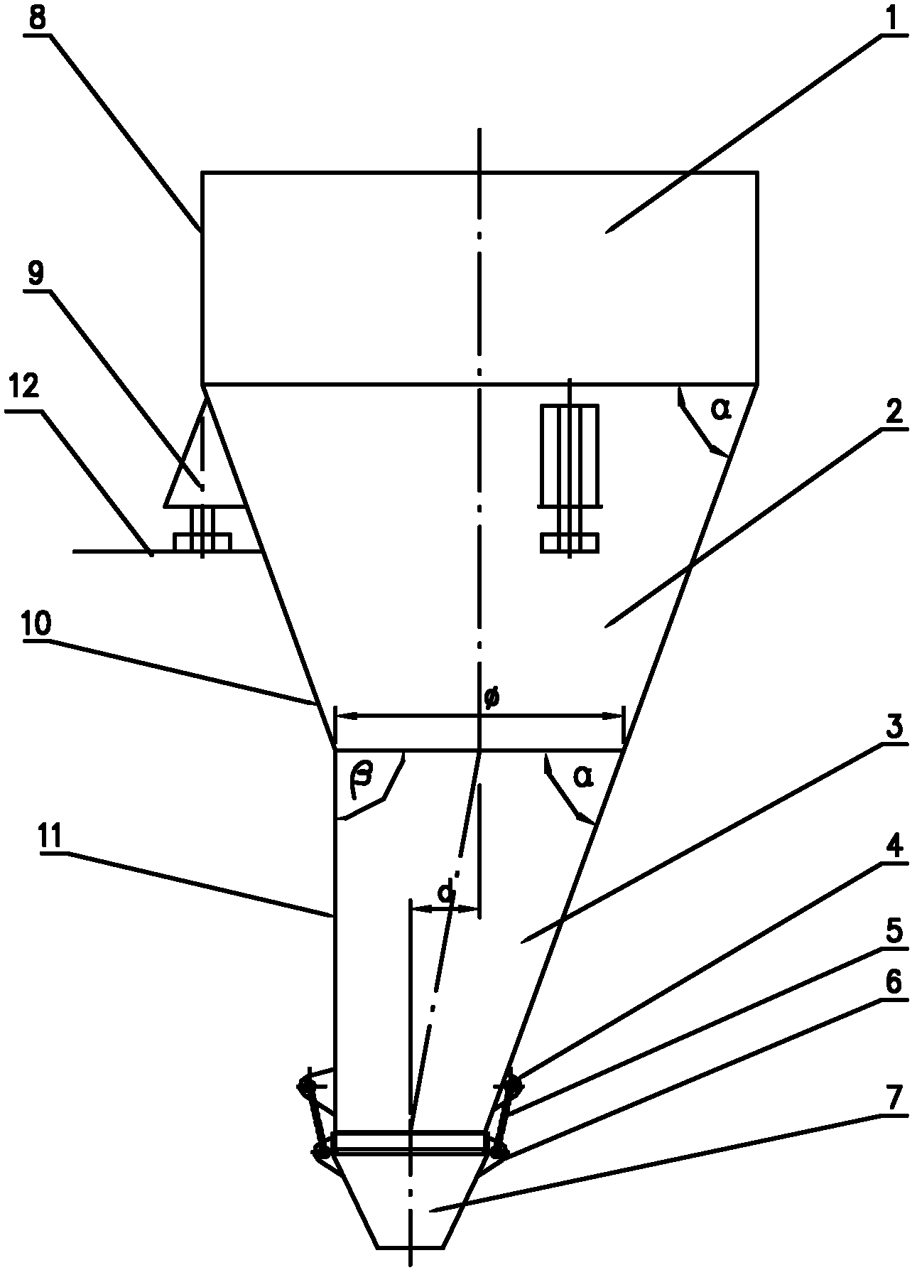
[0016] The present invention will be described in further detail below in conjunction with the accompanying drawings. Such as figure 1 As shown, the present invention discloses an anti-blocking raw coal bunker, which consists of four sections: a straight tube section 1, a circular platform section 2, an eccentric circular platform section 3, and a movable section 7. The straight cylinder section 1, the circular platform section 2, the eccentric circular platform section 3 and the movable section 7 are all made of steel plates. The circular platform section 2 and the eccentric circular platform section 3 connected under the straight cylinder section 1 are connected by welding. The eccentric circular platform section 3 is an asymmetric structure. The angle β between the section wall 11 and the horizontal plane is 90°. The eccentric distance d of the eccentric circular platform section 3 is not less than 30% of the radius φ on the eccentric circular platform section. The lower...


PUM


Abstract

The invention discloses an anti-blockage raw coal cabin, which consists of a straight tube section, a round table section, an eccentric round table section and a movable section, wherein the round table section and the eccentric round table section are respectively connected under the straight tube section, the eccentric round table section is in an asymmetrical structure, the eccentric round table section and the movable section are movably connected through a lifting chain, and a vibration motor is arranged on the outer wall of the movable section. The asymmetrical structure is adopted at the eccentric round table section for realizing the arch breaking through damaging the accumulated balance force of materials, and the arch forming prevention effect is good. The lower part of the eccentric round table section is sheathed into the movable section, the raw coal leakage during the vibration is prevented, and the environment protection requirement is met. The movable section is connected with the eccentric round table section through a short lifting annular chain, and the flexibility is good. The vibration motor is arranged on the movable section, when a material cabin is blocked, the vibration motor is started, the movable section and the fixed section at the upper part are staggered, the vibration effect is good, and the material cabin blockage phenomenon is effectively eliminated.

Description

technical field [0001] The invention relates to the field of coal powder preparation, in particular to a raw coal bunker with an anti-blocking function. Background technique [0002] In industries such as thermal power generation, metallurgy, coal chemical industry and building materials, raw coal needs to be made into coal powder as fuel or raw material. In the process of coal powder preparation, in order to ensure the stability and reliability of the pulverization system, it is generally necessary to set up a certain number of raw coal bunkers to play a role of storage or buffer. The lower part of the raw coal bunker is generally a symmetrical round platform or edge platform structure, which is made of reinforced concrete or steel structure. The silo with a symmetrical structure, when the material is stored in the silo to a certain amount during the falling process, due to the pressure of the silo, the viscosity between the raw coal, and the balance force of accumulation,...

Claims


Application Information

Patent Timeline
IPC IPC(8): B65D88/66B65D88/28
Inventor 周少丰汤楚雄闫朝付周强阮建波司敬芝
Owner WISDRI ENG & RES INC LTD
Features
  • Generate Ideas
  • Intellectual Property
  • Life Sciences
  • Materials
  • Tech Scout
  • Unparalleled Data Quality
  • Higher Quality Content
  • 60% Fewer Hallucinations
Learn More