
Mass tuned grain damper

A particle damper and tuning quality technology, which is applied to building components, shockproof and other directions, can solve the problems of high price of energy dissipation dampers, large local stress in the structure, inflexible installation position, etc. The effect of simple construction

Inactive Publication Date: 2012-04-25
BEIJING UNIV OF TECH
View PDF2 Cites 30 Cited by
  • Summary
  • Abstract
  • Description
  • Claims
  • Application Information

AI Technical Summary

Problems solved by technology

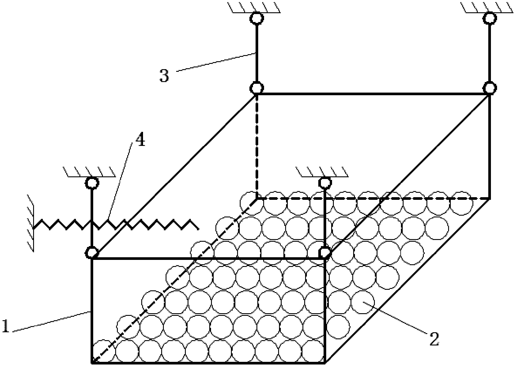
[0004] In order to solve the problem that the traditional tuned mass damper has a narrow tuning frequency band, setting an energy-dissipating damper is expensive, the installation position is not flexible, only provides additional damping to the local structure, and may cause excessive local stress of the structure, the present invention proposes a A kind of particle damper with tuning mass and friction collision energy dissipation function by setting a one-way hinge system and a return spring that can swing along the main direction of structural vibration

Method used


Image

  • Mass tuned grain damper
  • Mass tuned grain damper
  • Mass tuned grain damper

Examples


Embodiment 1

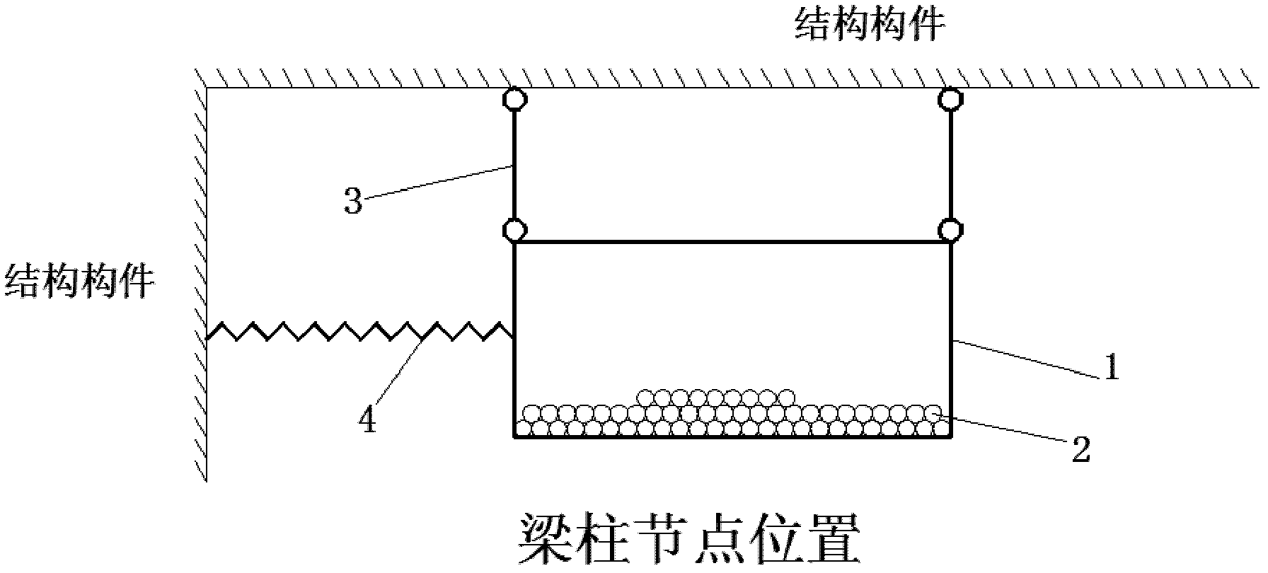
[0025] Such as figure 2 As shown, it is an embodiment of a tuned mass particle damper of the present invention, which mainly includes a damper cavity 1, a damping particle group 2 placed in the damper cavity at a certain stack height, a one-way hinge system 3, a reset The spring 4, and the embedded part embedded in the structural member.

[0026] The damper cavity 1 is a cuboid empty box welded by steel plates with a thickness of 3 mm to 5 mm. The damper cavity 1 and the embedded parts in the structural components are welded together through the one-way hinge system 3, and the damper is suspended from the building. Structural beam-column joints. The stacking height of the damping particle group 2 and the size of the damper cavity should be obtained according to the fundamental frequency of the structure or component based on relevant theories, and the stacking height of the damping particle group should not exceed 1 / 5 of the cavity height. Steel balls with a small friction ...

Embodiment 2

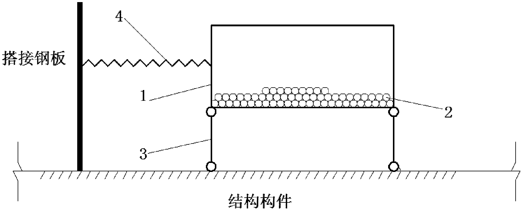
[0028] Such as image 3 As shown, it is an embodiment of a tuned mass particle damper of the present invention, which mainly includes a damper cavity 1, a damping particle group 2 placed in the damper cavity at a certain stack height, a one-way hinge system 3, a reset The spring 4, and the embedded parts and lapped steel plates pre-embedded in the structural components.

[0029] The damper cavity 1 is a cylindrical empty box welded by 3mm to 10mm thick steel plates. The damper is supported on the equipment floor of the building structure or the bottom plate of the box girder of the bridge structure by means of a one-way hinge system. The stacking height of the damping particle group 2 and the size of the damper cavity should be obtained according to the fundamental frequency of the structure or component based on relevant theories, and the stacking height of the damping particle group should not exceed 1 / 5 of the cavity height. As the damping particle material, steel balls wi...


PUM


Abstract

The invention relates to a mass tuned grain damper and belongs to the field of building shock absorption. The mass tuned grain damper comprises a damper cavity, damping grain groups, a one-way hinge system and a resetting spring, wherein the damping grain groups are uniformly placed in the damper cavity; an embedded part in a building structure or bridge structure is fixedly connected to the damper cavity by the one-way hinge system; and the resetting spring is arranged outside the damper cavity, thereby forming a substructure with a certain mass and a certain natural frequency of vibration. Under the effect of wind and / or an earthquake, the mass tuned grain damper can oscillate back and forth along the arrangement direction of the resetting spring so as to tune the natural frequency of vibration of the structure. Under the actions of the rolling or sliding, friction and colliding of the damping grain groups in the damper cavity, the kinetic energy of the structure can be transferred and consumed, the distribution additional damping is supplied to the structure in a flexible and scattered arranging mode, thereby restraining the structure vibration and ensuring the structure safety.

Description

technical field [0001] The invention relates to a particle damper with tuning quality and frictional collision energy consumption function by setting a one-way hinge system and a return spring that can swing along the main direction of structural vibration, and belongs to the technical field of anti-seismic, shock-absorbing and wind-resistant structural engineering. Background technique [0002] The tuned mass damper (TMD) or tuned liquid damper (TLD) vibration reduction control technology developed rapidly in recent years has attracted widespread attention due to its characteristics of small changes to the original structure, simple construction, and remarkable vibration damping effect. The tuning system is a shock-absorbing control system that sets inertial mass at the position where the structure vibrates greatly or adds flowing liquid inside the subsidiary structure, and is equipped with springs and dampers to control the dynamic displacement or acceleration of the struct...

Claims


Application Information

Patent Timeline
Patent Type & Authority Applications(China)
IPC IPC(8): E04B1/98
Inventor 闫维明王瑾许维炳侯立群李德月
Owner BEIJING UNIV OF TECH
Learn More