Micron-level powder material sieving equipment and sieving method

A material sieve and micron-level technology, which is applied in chemical instruments and methods, solid separation, and separation of solids from solids with airflow, etc., can solve the problems of bulky, low screening efficiency, and high maintenance costs

Active Publication Date: 2012-05-02
李文胜
View PDF4 Cites 10 Cited by
  • Summary
  • Abstract
  • Description
  • Claims
  • Application Information

AI Technical Summary

Problems solved by technology

However, this kind of airflow sieving machine has exposed the following problems in long-term use: 1) It is necessary to use cyclone separator baffles and heavy objects. The equipment has complex structure, high equipment cost, high maintenance cost, large volume and large floor space. , which is neither easy to maintain nor conducive to popularization and application; 2) There is a special screening machine, the structure of which is complex, the cost of equipment is high, maintenance is inconvenient, and energy consumption is large; 3) There is an arc-shaped air intake pipe above the screening machine , there are airflow ducts between the air inlet of the fan and the screening machine, and between the air outlet of the screen...

Method used


Image

  • Micron-level powder material sieving equipment and sieving method
  • Micron-level powder material sieving equipment and sieving method
  • Micron-level powder material sieving equipment and sieving method

Examples


Embodiment 1

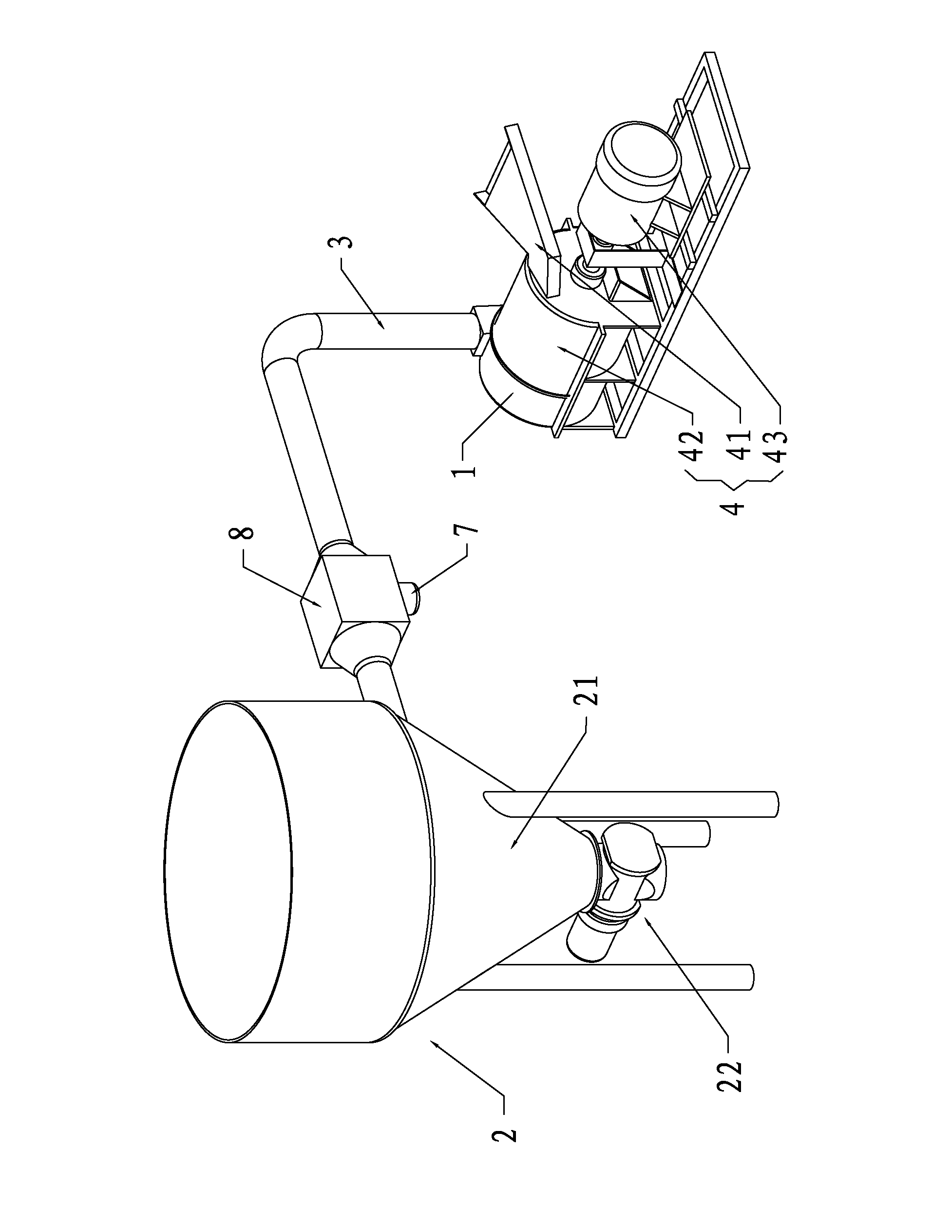
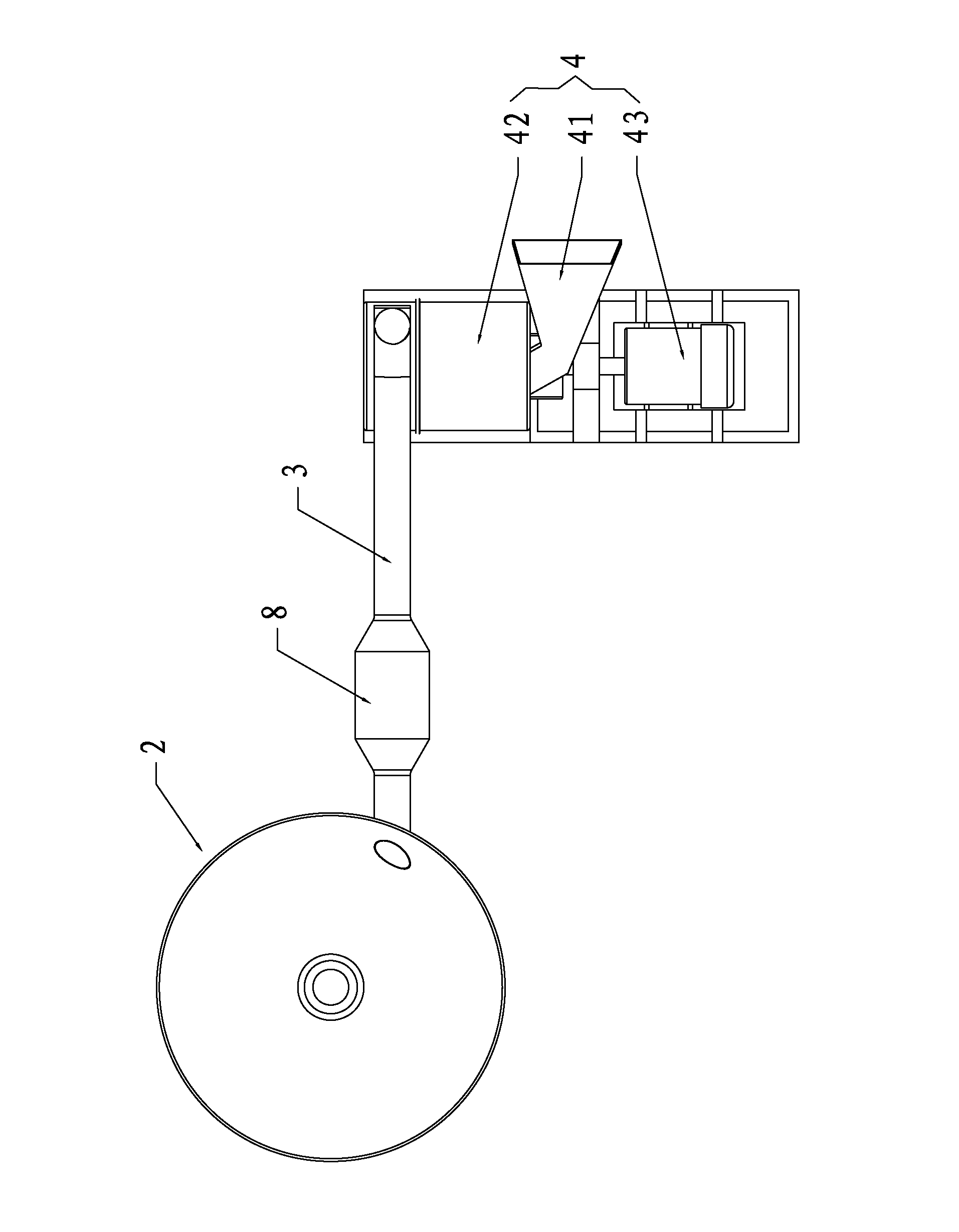
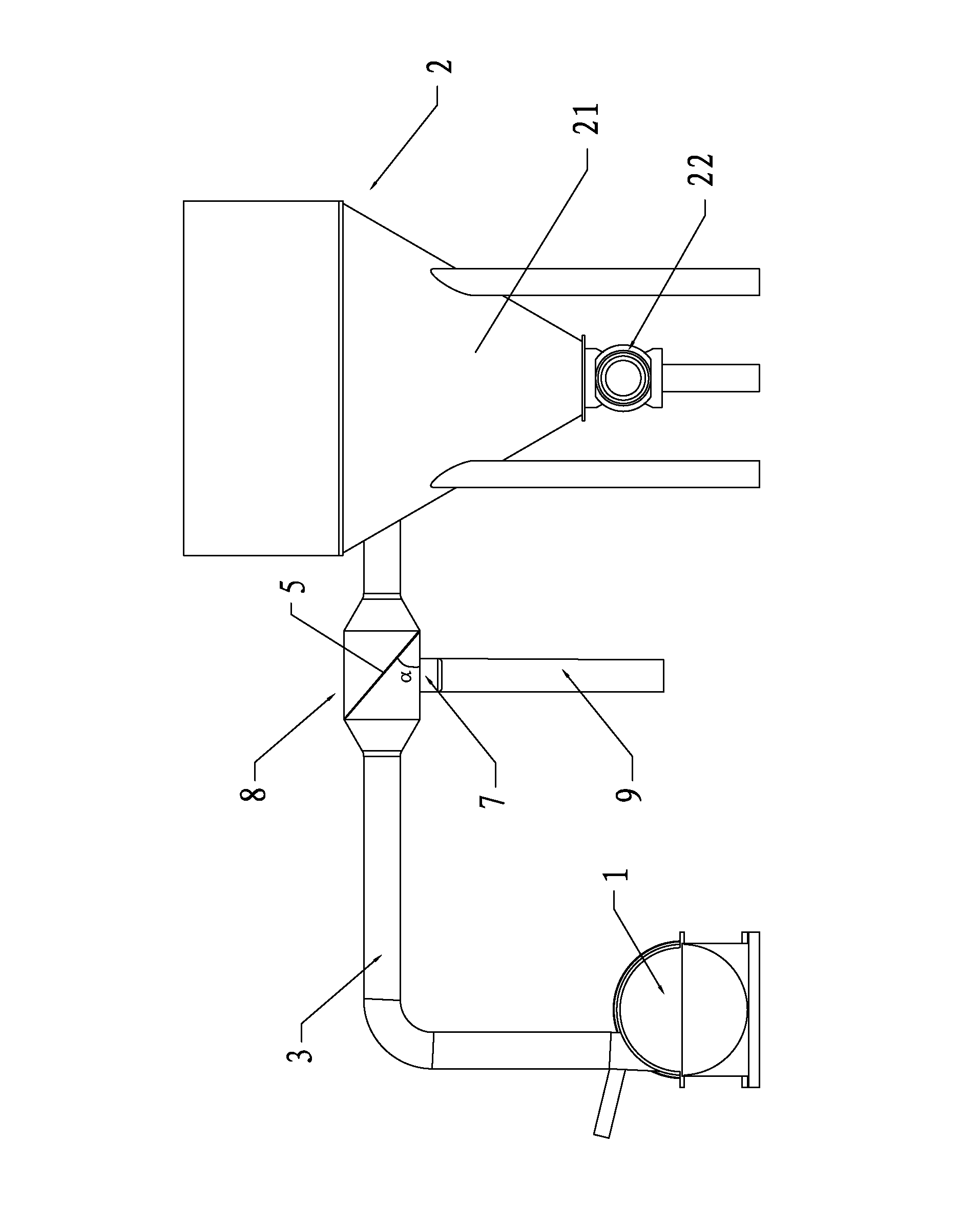
[0042] Such as Figure 1 to Figure 5 As shown, the screening equipment for micron-sized powder materials in this embodiment includes an air supply device 1, a collection device 2, and an airflow duct 3 arranged between the air supply device 1 and the collection device 2, so that The air supply device 1 is connected with a feeding device 4, and the position of the air flow duct adjacent to the collecting device 2 is provided with a screen slot 5, and the screen slot 5 is arranged obliquely, and the inclination angle is 20-80 degrees, so The screen slot 5 is inserted with a screen insert 6 cooperating with the screen slot 5, and the screen insert 6 is detachably laid with a screen, and the air flow duct 3 is adjacent to the screen A coarse material outlet 7 is provided at the lower end of the slot 5 .

[0043] When in use, start the air supply device 1, and the powder material to be screened will be blown to the screen by the strong airflow generated by the air supply device 1 ...

Embodiment 2

[0062] Such as figure 1 As shown, the difference between this embodiment and Embodiment 1 is that the feeding device 4 of this embodiment includes a pulverizer 42 connected to the air supply device 1, and the pulverizer 42 is connected to the air supply device 1 Both are driven and connected to a motor 43 through a motor shaft. The pulverizer 42 is connected to a hopper 41 , and a discharge regulating plate is provided at the lower end of the hopper 41 .

[0063] The air supply device 1 of the present embodiment is connected with a pulverizer 42, and the pulverizer 42 is arranged in front of the air outlet of the air supply device 1, and the raw materials are put into the hopper 41, and the feeding speed and the feeding speed of the raw materials are controlled by the discharge regulating plate. The amount of material, the pulverizer 42 crushes the raw materials into micron-sized powder materials, and the air supply device 1 blows the crushed powder materials to the screen for...

Embodiment 3

[0073] Such as figure 1 As shown, the difference between this embodiment and Embodiment 1 is that a hollow sieve body 8 is connected between the tail end of the airflow duct 3 of this embodiment and the collection device 2, and the sieve slot 5 It is arranged on the sieve body 8 , the two ends of the sieve body 8 communicate with the airflow duct 3 respectively, and the cross-sectional area of ​​the sieve body 8 is larger than the cross-sectional area of ​​the airflow duct 3 .

[0074] Specifically, the sieve body 8 is hollow and has a slightly smaller cylindrical shape at both ends, the sieve body 8 is arranged in parallel with the airflow duct 3, and the inner diameter of the sieve body 8 is larger than the inner diameter of the airflow duct 3, The screen slot 5 is welded to the screen body 8 . The two ends of the sieve body 8 are slightly smaller to ensure a stable connection between the sieve body 8 and the gas flow pipe 3, and the air tightness is good, which can effecti...


PUM

PropertyMeasurementUnit
Meshaaaaaaaaaa

Abstract

The invention relates to the technical field of sieving equipment, in particular to micron-level powder material sieving equipment and a sieving method thereof. The micron-level powder material sieving equipment comprises an air supply device, a material collecting device and an airflow pipeline arranged between the air supply device and the material collecting device; the air supply device is connected with a feeding device; the position of the airflow pipeline near the material collecting device is provided with a sieve screen slot; the sieve screen inserting slot is arranged obliquely; theinclined angle is 20-80 degrees; the sieve screen inserting slot is provided with a sieve screen inserting plate which is matched with the sieve screen inserting slot; a sieve screen is detachably paved on the sieve screen inserting plate; and the position of the airflow pipeline near the lower end of the sieve screen inserting slot is provided with a coarse material outlet. According to the invention, the airflow and powder materials are mixed uniformly, and the powder materials are fully atomized; moreover, the micron-level powder material sieving equipment has the characteristics of simplified technique, low production cost, high sieving efficiency, good sieving effect, high efficiency, energy saving, and convenience for widespread popularization and application.

Description

technical field [0001] The invention relates to the technical field of screening equipment, in particular to a screening equipment and screening method for micron-sized powder materials. Background technique [0002] Screening machine, also known as powder sieving machine, uses the relative movement of bulk materials and the screen surface to make some particles pass through the sieve holes, and divide sand, gravel, crushed stone and other materials into different levels of vibrating screens according to particle size. Sub-machinery. [0003] At present, most of the powder separation equipment adopts vibrating sieving machine. When sieving solid particle materials, this kind of sieving machine relies on the reciprocating motion or vibration of the screen surface to leak the solid particles on the screen from the screen, and will be larger than the screen. The pore-sized particles are discharged from the coarse material outlet. Due to the use of specific power equipment such...

Claims


Application Information

Patent Timeline
IPC IPC(8): B07B7/06
Inventor 李文胜
Owner 李文胜
Why Eureka
Try Eureka