Optical fiber beam combiner and manufacturing method thereof

An optical fiber combiner and manufacturing method technology, which is applied in the field of pump laser beam combiners, can solve the problems that the optical fiber combiner cannot withstand, the power loss at the fusion point is large, and the structure of the fiber waveguide is damaged, so as to overcome the laser resistance The effect of low power, increased strength, and improved pump coupling efficiency

Inactive Publication Date: 2012-05-02
FENGHUO COMM SCI & TECH CO LTD
View PDF10 Cites 19 Cited by
  • Summary
  • Abstract
  • Description
  • Claims
  • Application Information

AI Technical Summary

Problems solved by technology

Chinese patents with application numbers 201110062467.5 and 200910110240.6 and US patents with application numbers US6,900,933 and US7,492,993 respectively propose an end-pumped optical fiber combiner and its manufacturing method. After the taper, an output passive fiber is fused. The biggest defect of the fiber combiner is that: the taper destroys the waveguide structure of the fiber, and the power loss at the fusion point is large. The fiber combiner cannot withstand large pump power and is easily damaged.
The US patent application number US6,490,388 proposes a side-pumped fiber combiner, which welds the passive fiber to the side of the active fiber, disperses the pump power, and to a certain extent The laser power level of the optical fiber is improved, but this manufacturing method is not only difficult in the fusion process, but it is easy to burn out if the fusion is not good, and the fusion method damages the optical fiber to a certain extent, and the damaged point is easy to be burned out

Method used


Image

  • Optical fiber beam combiner and manufacturing method thereof
  • Optical fiber beam combiner and manufacturing method thereof
  • Optical fiber beam combiner and manufacturing method thereof

Examples


Embodiment 1

[0033] Example 1: Active fiber glass rod is D-shaped

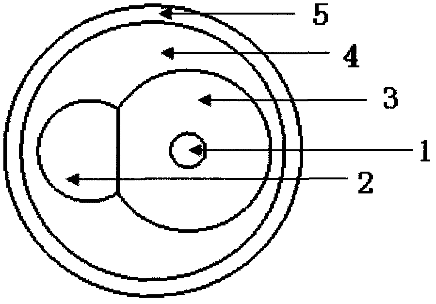
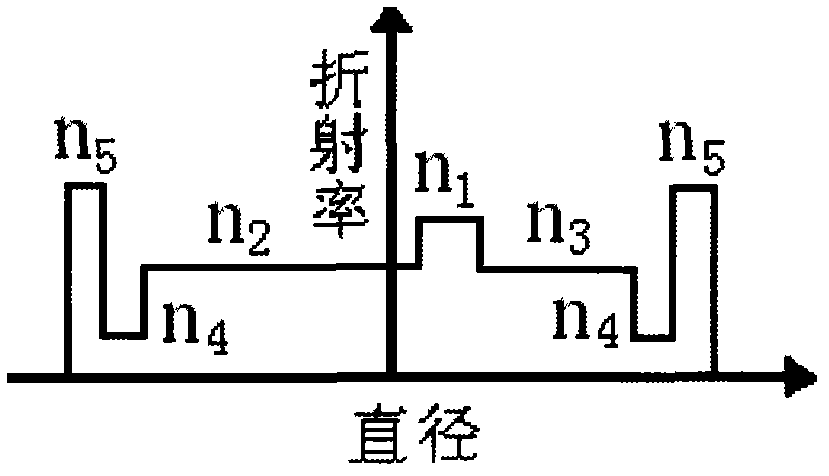
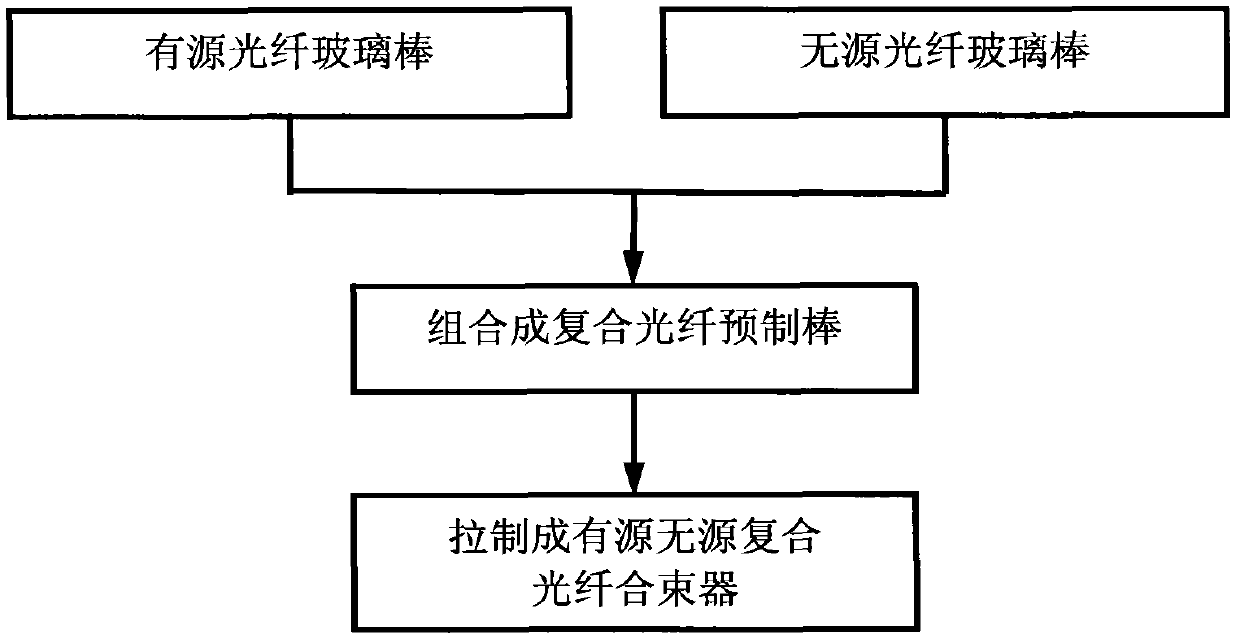
[0034] Take a pre-prepared ytterbium-doped silica glass rod (active fiber), the diameter of the ytterbium-doped core layer is 0.9mm, and the refractive index n of the core 1 of the active fiber 1 =1.4592, the diameter of the silica cladding (the inner cladding 3 of the active fiber) is 18mm, and the refractive index is n 3 =1.4571, grind it into a D shape, and the grinding thickness of the glass rod is 2.25mm; 2 =1.4571, its diameter is 12mm, and the grinding thickness of the glass rod is 2.65mm; then, the D-shaped straight edge of the ytterbium-doped quartz glass rod and the D-shaped straight edge of the coreless pure quartz glass rod are spliced ​​along the axial direction to form Composite fiber preform.

[0035] The composite optical fiber preform is placed on the drawing tower equipment, and the high temperature furnace is heated to 1900 ℃. 4 The UV-curable acrylic paint with = 1.37 is coated on the glass fiber, an...

Embodiment 2

[0037] Example 2: Active fiber glass rod is hexagonal

[0038] Take a pre-prepared ytterbium-doped silica glass rod (active fiber), the diameter of the ytterbium-doped core layer is 1.0mm, and the refractive index n of the core 1 of the active fiber 1 =1.4586, the diameter of the silica cladding (inner cladding 3 of the active fiber) is 15.0 mm, and the refractive index is n 3 =1.4571, grind it into a hexagonal shape, and the grinding thickness of each side of the glass rod is 1.0mm; 2 =1.4571, its diameter is 15mm, and the grinding thickness of the glass rod is 3.70mm; then, a straight edge of the ytterbium-doped quartz glass rod and a straight edge of the coreless pure quartz glass rod are spliced ​​along the axial direction to form a composite Optical fiber preform.

[0039] The composite optical fiber preform is placed on the drawing tower equipment, and the high temperature furnace is heated to 2100 ℃. 4 The UV-curable acrylic paint of = 1.37 is coated on the glass fib...

Embodiment 3

[0041] Example 3: The active optical fiber glass rod is octagonal

[0042] Take a pre-prepared ytterbium-doped silica glass rod (active fiber), the diameter of the ytterbium-doped core layer is 1.5mm, and the refractive index n of the core 1 of the active fiber 1 =1.46036, the diameter of the silica cladding (inner cladding 3 of the active fiber) is 30mm, and the refractive index is n 3 =1.4571, grind it into an octagonal shape, and the grinding thickness of each side of the glass rod is 1.15mm; 2 = 1.4571, its diameter is 20mm, and the grinding thickness of the glass rod is 2.0mm; then, a straight edge of the ytterbium-doped silica glass rod and a straight edge of the coreless pure silica glass rod are spliced ​​along the axial direction to form a composite optical fiber preform.

[0043] The composite optical fiber preform is placed on the drawing tower equipment, and the high temperature furnace is heated to 2200 ℃. 4 The UV-curable acrylic paint of = 1.37 is coated on t...


PUM


Abstract

The invention discloses an optical fiber beam combiner and a manufacturing method thereof. The optical fiber beam combiner comprises active optical fiber and passive optical fiber, wherein the active optical fiber and the passive optical fiber are combined along an axial surface or contacted along an axial line. The manufacturing method for the optical fiber beam combiner comprises the following steps of: axially combining an active optical fiber glass rod with a passive optical fiber glass rod to form a compound optical fiber preformed rod; drawing the compound optical fiber preformed rod into optical fiber to obtain the optical fiber beam combiner. The optical fiber beam combiner realizes the integration of the active optical fiber and the passive optical fiber and facilitates distributed pumping of all-optical fiber lasers, the pumping coupling efficiency is improved, the power consumption is small, the tolerance laser power level and the reliability are improved, the production efficiency is improved, the manufacturing cost is lowered, and the optical fiber beam combiner is suitable for large-scale production.

Description

technical field [0001] The invention relates to a pump laser beam combiner used in the field of high-power fiber lasers, in particular to a fiber beam combiner and a manufacturing method thereof. Background technique [0002] Fiber lasers belong to the third generation of lasers. Because of their advantages of good beam quality, high efficiency, long service life, high reliability, small size and convenient use, they have been gradually applied in laser marking machines, laser cutting, laser welding and large Power laser devices and other fields. [0003] In order to manufacture high-power fiber lasers, multiple pump lasers need to be coupled into active fibers (such as double-clad ytterbium-doped fibers) to achieve high-power laser output. Scientists in various countries have tried many technologies, among which the most Common is the use of pump combiner technology. Among the various pump combiner technologies, the most common are side pump combiners and end pump combine...

Claims


Application Information

Patent Timeline
Patent Type & Authority Applications(China)
IPC IPC(8): G02B6/26G02B6/255
Inventor 陈伟李诗愈罗文勇莫琦杜城柯一礼胡福明张涛赵磊
Owner FENGHUO COMM SCI & TECH CO LTD
Why Eureka
Try Eureka