Laser optical tweezer microscope

A technology of microscope and microscopic objective lens, which is applied in the field of micro-optics and nanometers, can solve the problems of precision limitation and difficulty, and achieve the effect of increasing the moving speed, convenient operation and increasing the number of optical tweezers

Inactive Publication Date: 2012-05-02
李志扬
View PDF4 Cites 18 Cited by
  • Summary
  • Abstract
  • Description
  • Claims
  • Application Information

AI Technical Summary

Problems solved by technology

However, the use of holographic dry plates generally can only produce static optical tweezers. Although the number of optical tweezers can be increased a lot, it is very difficult to dynamically move optical tweezers, especially to move each optical tweezers independently according to any path, because the holographic dry plate The interference fringes on the fixed
Although the use of spatial light modulators can dynamically generate and move optical tweezers through optical wavefront control, the accuracy is still limited to a certain extent, because the size of each pixel of the spatial light modulator is generally much larger than the optical wavelength.

Method used


Image

  • Laser optical tweezer microscope
  • Laser optical tweezer microscope
  • Laser optical tweezer microscope

Examples


Embodiment 1

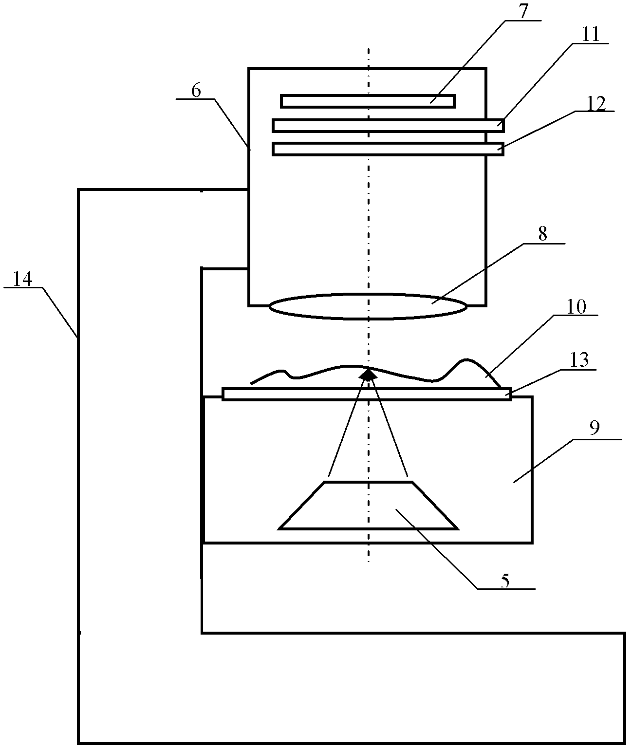
[0030] figure 2 A schematic diagram of the structure of a laser optical tweezers microscope working in reflection mode is given. It includes a lens barrel 6, an image sensor 7, a microscope objective lens 8, a movable stage 9 up and down, a substrate 13, a support 14, and digital optics for generating laser optical tweezers and focusing the optical tweezers on an object 10. The phase conjugation device 5, the lens barrel 6 is fixed on the support 14, the movable stage 9 is connected to the support 14 through the rack, and the substrate 13 is placed on the movable stage 9, which is used for The object 10 placed on the substrate 13 is placed on the bottom of the lens barrel 6 for magnifying and imaging the object 10, and the image sensor 7 for recording the magnified microscopic image is arranged in the lens barrel 6 and positioned at the microscope objective 8. above. Since the digital optical phase conjugation device 5 is fixed together with the stage 9 of the digital optical...

Embodiment 2

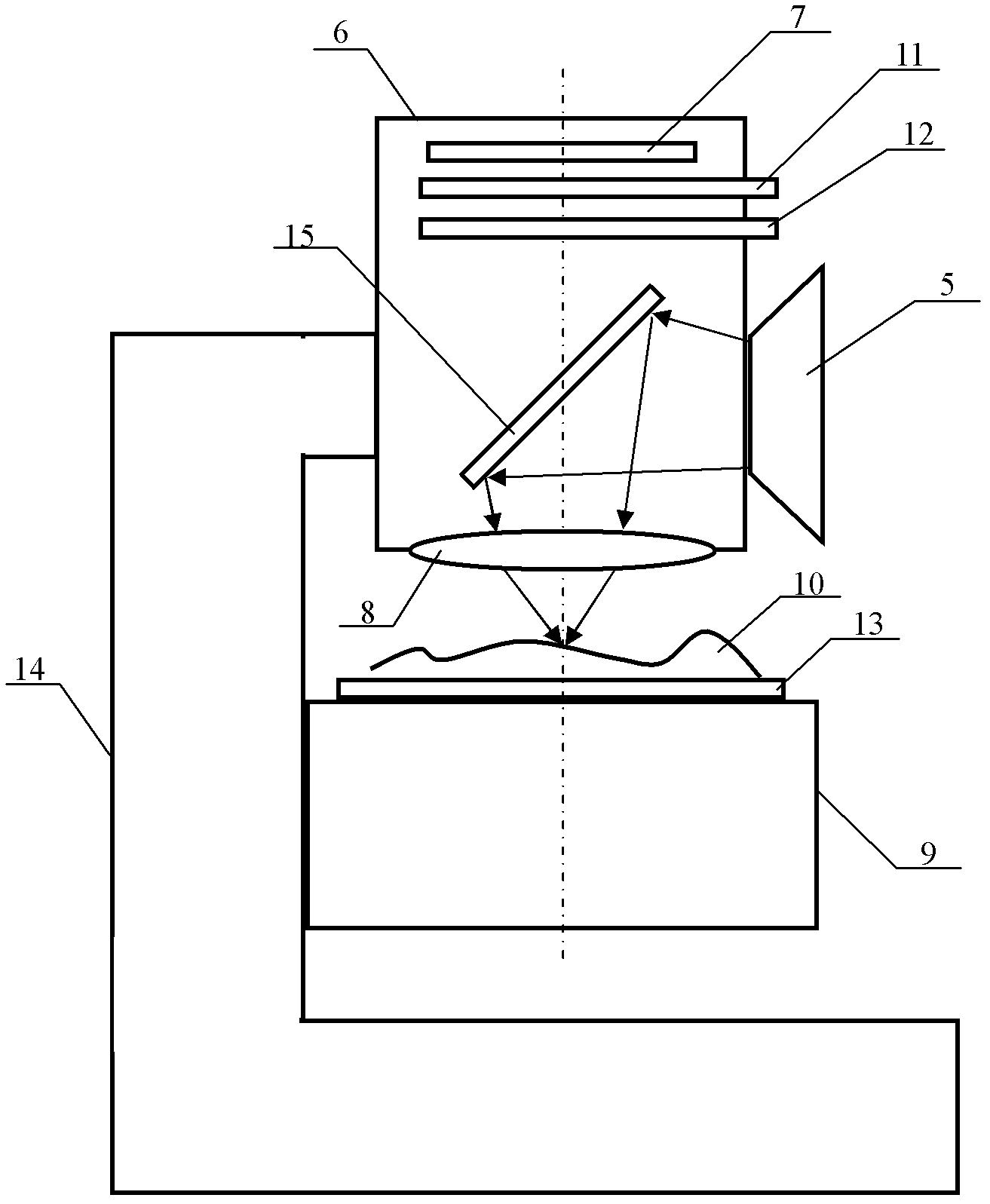
[0036] image 3 A schematic diagram of the structure of a laser optical tweezers microscope working in reflection mode is given, with figure 2 Compared with the laser optical tweezers microscope working in the transmission mode, it also includes a half-mirror 15, and the half-mirror 15 is arranged in the lens barrel 6 and is located between the microscope objective lens 8 and the image sensor 7 , the reflective surface of the half mirror 15 is placed at 45 degrees to the optical axis of the microscope objective lens 8, and the digital optical phase conjugation device 5 is arranged on the side of the lens barrel, so that the laser light produced by the digital optical phase conjugation device 5 The tweezers focus on the object 10 placed on the object-carrying substrate 13 from above after being reflected by the half-mirror 15 and refracted by the microscope objective lens 8 .

[0037] and figure 2 Compared with the arrangement shown, the major difference lies in the focusin...


PUM


Abstract

The invention relates to a laser optical tweezer microscope. The microscope comprises: a lens cone, an image sensor, a microscopic objective lens, an objective table which can move up and down, a carrying substrate, a support and a digital optical phase conjugate apparatus which is used to generate laser optical tweezer and focus the optical tweezer on an object. The lens cone is fixed on the support. The objective table which can move up and down is connected with the support through a rack. The carrying substrate is placed on the objective table which can move up and down. The microscopic objective lens, which is used to carry out amplification imaging to the object placed on the carrying substrate, is installed on a bottom of the lens cone. The image sensor, which is used to record and amplify the microscopic image, is arranged in the lens cone and is located above the microscopic objective lens. By using the microscope of the invention, focusing accuracy and positioning accuracy of the optical tweezer can be increased. A precision machinery motor is not needed to increase a moving speed of the optical tweezer. An optical tweezer number can be increased. Any one optical tweezer can be independently operated. Through cooperation of a plurality of the optical tweezers, a high-precision complex microscopic operation can be realized.

Description

technical field [0001] The invention belongs to the field of micro-optics and nanotechnology, and more specifically relates to a laser optical tweezers microscope, which is suitable for manipulation, transportation, testing, assembly, processing, and microscopic three-dimensional measurement of cells, DNA, nanoparticles, and nanostructures. Background technique [0002] In the fields of life science, chemistry, nanotechnology, etc., it is necessary to perform various manipulations and tests on tiny objects, such as cell nuclei, DNA chains, molecular groups, and micro-mechanical structures, such as handling, cutting, peeling, grafting, injection, assembly, and curing. , activation, fluorescence detection, electrophoresis detection, etc. Common microscopic manipulation methods include mechanical probes, molecular tweezers, optical tweezers, etc., in which mechanical probes can puncture cells; molecular tweezers can adsorb cells on the front of capillaries to quantitatively meas...

Claims


Application Information

Patent Timeline
Patent Type & Authority Applications(China)
IPC IPC(8): G02B21/32G21K1/00
Inventor 李志扬
Owner 李志扬
Why Eureka
Try Eureka