Electrochemical grinding method and device for cam surface of internal-combustion engine

An electrochemical grinding, cam surface technology, applied in grinding devices, grinding machine tools, metal processing equipment, etc., can solve the problems of cam grinding cracks, irregular cam contour lines, burns, etc., and achieve high finishing efficiency and technology. Simple equipment and easy maintenance

Inactive Publication Date: 2012-05-23
CHANGZHOU TIANSHAN HEAVY IND MACHINERY
View PDF2 Cites 0 Cited by
  • Summary
  • Abstract
  • Description
  • Claims
  • Application Information

AI Technical Summary

Problems solved by technology

Since the cam curve is composed of several simple or complex curve connections, the cam profile is irregular, resulting in a sharp "jump" of speed and acceleration, and the instantaneous speed of the grinding point, the contact arc length of the grinding wheel and the workpiece, and The polar coordinate position of the grinding point relative to the cam center changes with the shape of the cam curve, which makes the grinding force, elastic deformation of the grinding wheel and workpiece system, and grinding heat constantly change, which can easily cause cam grinding defects - Grinding cracks and burns
Using a cam grinder with a profiler for fine grinding is prone to grinding defects, while using an imported CNC cam grinder is not easy to produce grinding defects, but imported CNC cam grinders are expensive, approaching tens of millions of RMB

Method used


Image

  • Electrochemical grinding method and device for cam surface of internal-combustion engine
  • Electrochemical grinding method and device for cam surface of internal-combustion engine

Examples


Embodiment Construction

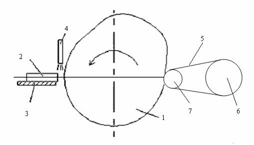
[0016] Such as figure 1 As shown, the entire internal combustion engine cam surface electrochemical compound abrasive belt grinding and finishing equipment is composed of a camshaft rotary motion system, an electrode motion system and an abrasive belt motion system.

[0017] The camshaft 1 is driven by the servo motor to rotate at a constant speed, the speed is 120r / min, and the camshaft is connected to the positive pole of the constant current DC power supply.

[0018] The electrode 2 is placed on the CNC table 3, and the servo motor drives the CNC table 3 to move back and forth, thereby driving the electrode 2 to move back and forth, and maintain a constant gap with the cam, the gap value is 5mm, and the electrode is connected to the negative pole of the constant current DC power supply .

[0019] A neutral electrolyte 4 is passed between the cam 1 and the electrode 2, and a constant DC voltage of 16V is applied between the cam 1 and the electrode 2.

[0020] The abrasive ...


PUM


Abstract

The invention relates to an electrochemical grinding method and an electrochemical grinding device for a cam surface of an internal-combustion engine, and relates to a burnishing technology of the cam surface of the internal-combustion engine. In the electrochemical grinding method and the electrochemical grinding device, a cam is connected to a positive electrode of a constant-current and direct-current power supply, an electrode is connected to a negative electrode of the constant-current and direct-current power supply, and neutral electrolyte is injected between the positive electrode and the negative electrode; after the direct-current power supply is powered on, a layer of passive film for preventing metal on the cam surface from being dissolved by direct current is formed on the cam surface, and a microcosmic high-point passive film on the cam surface is removed by the grinding of an abrasive belt to expose microcosmic high-point metal, so that the microcosmic high-point metal is dissolved by the direct current, and the passive film is formed on the cam surface sequentially; a microcosmic low-point passive film on the cam surface cannot be ground by the abrasive belt and exists in a microcosmic low point sequentially, so that the microcosmic low point passive film is prevented from being dissolved by the direct current; and by the repeated passivation-activation process, the cam surface can be burnished to a mirror surface. By the electrochemical grinding method and the electrochemical grinding device, the cam surface is burnished after coarse grinding, so that the roughness Ra of the cam surface is reduced to 0.10 micrometer further, and the accuracy of the cam can be kept.

Description

technical field [0001] The invention relates to a finishing technology for the cam surface of an internal combustion engine. Specifically, the surface finishing of the cam surface of the internal combustion engine is carried out by combining electrochemical action and abrasive belt grinding, and is mainly used for the last finishing process of the cam surface of the internal combustion engine. process. Background technique [0002] The camshaft is one of the key parts of the diesel engine, it controls the intake, oil supply and exhaust process of the diesel engine, the reliability of the camshaft is directly related to the normal operation of the diesel engine and the safe operation of the locomotive. The vast majority of domestic cam production adopts the process of "milling shape → rough grinding → heat treatment → fine grinding" for cam processing. Since the cam curve is composed of several simple or complex curve connections, the cam profile is irregular, resulting in a...

Claims


Application Information

Patent Timeline
IPC IPC(8): B24B37/02B24B21/02
Inventor 王辉
Owner CHANGZHOU TIANSHAN HEAVY IND MACHINERY
Why Eureka
Try Eureka