Supercharge Your Innovation With Domain-Expert AI Agents!

Fluid for removing coating film formed by csd, method for removing csd coating film using same, and ferroelectric thin film and process for producing same

A manufacturing method and coating film technology, which is applied in semiconductor/solid-state device manufacturing, circuits, electrical components, etc., can solve the problems of easy cracks in the film and the decline of equipment qualification rate, so as to prevent pollution, prevent the formation of sediment, The effect of low penetrating power

Active Publication Date: 2012-05-23
MITSUBISHI MATERIALS CORP
View PDF15 Cites 0 Cited by
  • Summary
  • Abstract
  • Description
  • Claims
  • Application Information

AI Technical Summary

Problems solved by technology

[0005] In the sol-gel method (hereinafter collectively referred to as the CSD method, and its solution is referred to as the raw material solution), when the film thickness is too thick, cracks are likely to occur in the film after heat treatment, and the film peeled off at the cracks becomes particles, which will cause It becomes the cause of the decline in the pass rate of the equipment

Method used


Image

  • Fluid for removing coating film formed by csd, method for removing csd coating film using same, and ferroelectric thin film and process for producing same
  • Fluid for removing coating film formed by csd, method for removing csd coating film using same, and ferroelectric thin film and process for producing same
  • Fluid for removing coating film formed by csd, method for removing csd coating film using same, and ferroelectric thin film and process for producing same

Examples


Embodiment 1)

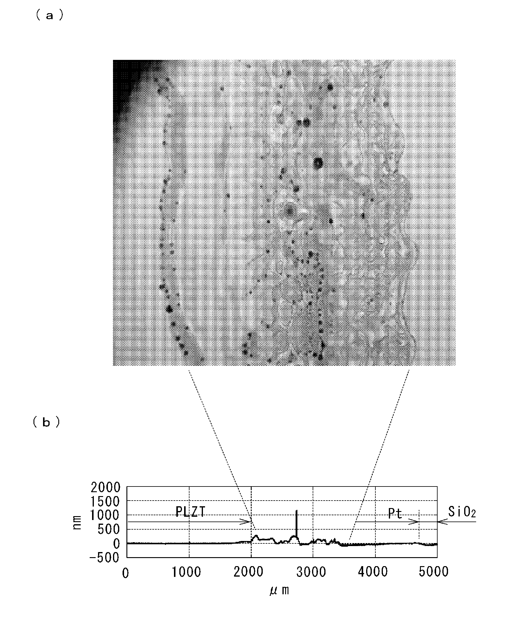
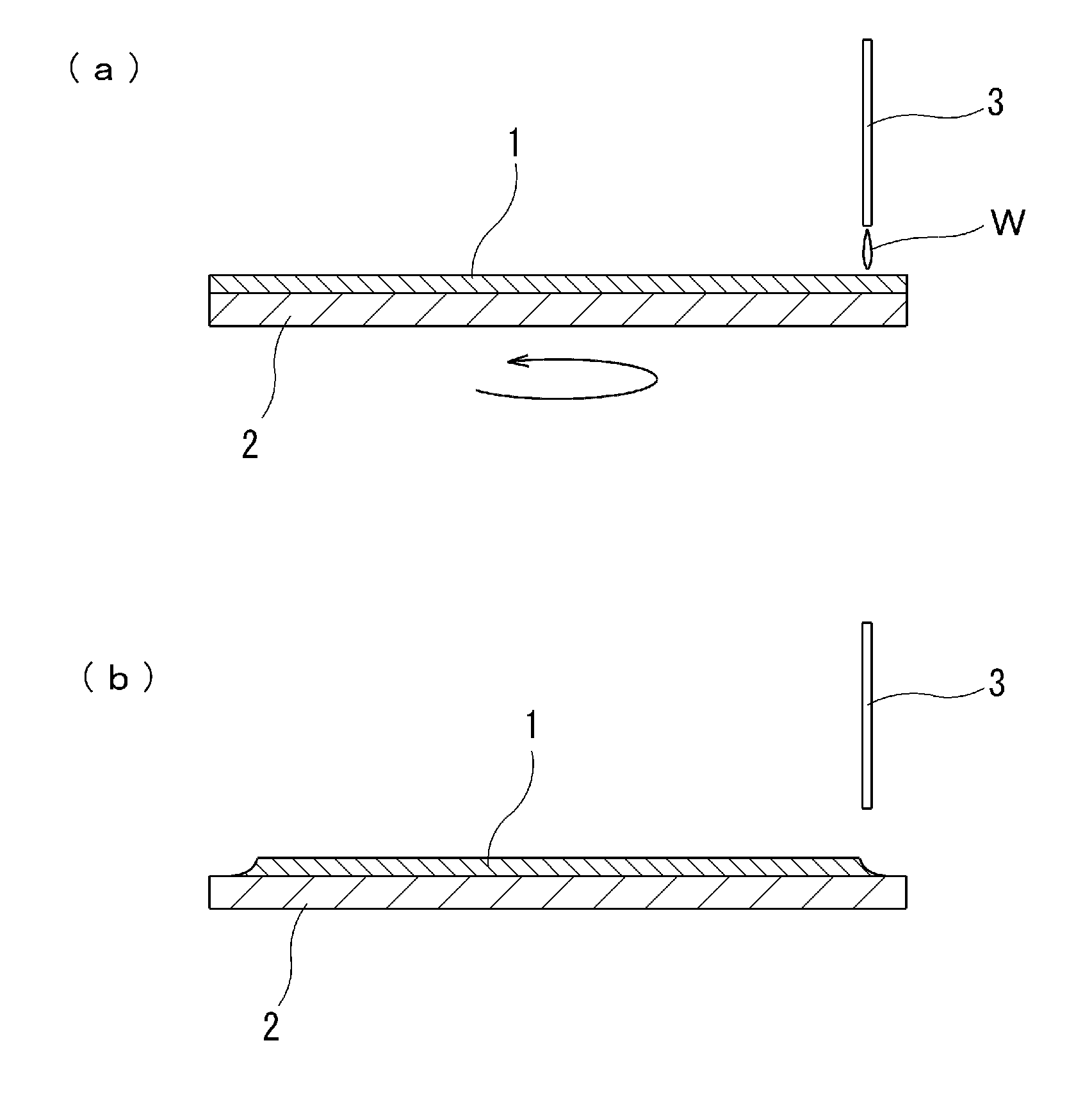
[0091] Next, as Example 1, in the same Pt / SiO 2 / Si substrate is the same as the method of the above-mentioned preliminary experiment. After spin-coating 10wt% raw material solutions 1-1~1-6, in order to avoid the Pb-containing film and SiO 2 In the reaction during firing, while the substrate is rotated at 2500 rpm with a spin coater, liquids 1 to 62 for removal are sprayed at positions 5 mm inward in the radial direction from the outer peripheral edge of the substrate to dissolve the gel-like coating film. EBR processing. The liquids 1 to 62 for removal contained an organic solvent and water at a predetermined weight ratio as shown in Table 5 and Table 6. Among them, the removal liquids 1 to 50 contain one type of organic solvent X and water, and the removal liquids 51 to 61 contain an organic solvent in which two types of organic solvents X and Y are mixed in a predetermined weight ratio, and water. The liquid 62 for removal is water and does not contain an organic solvent...

Embodiment 2)

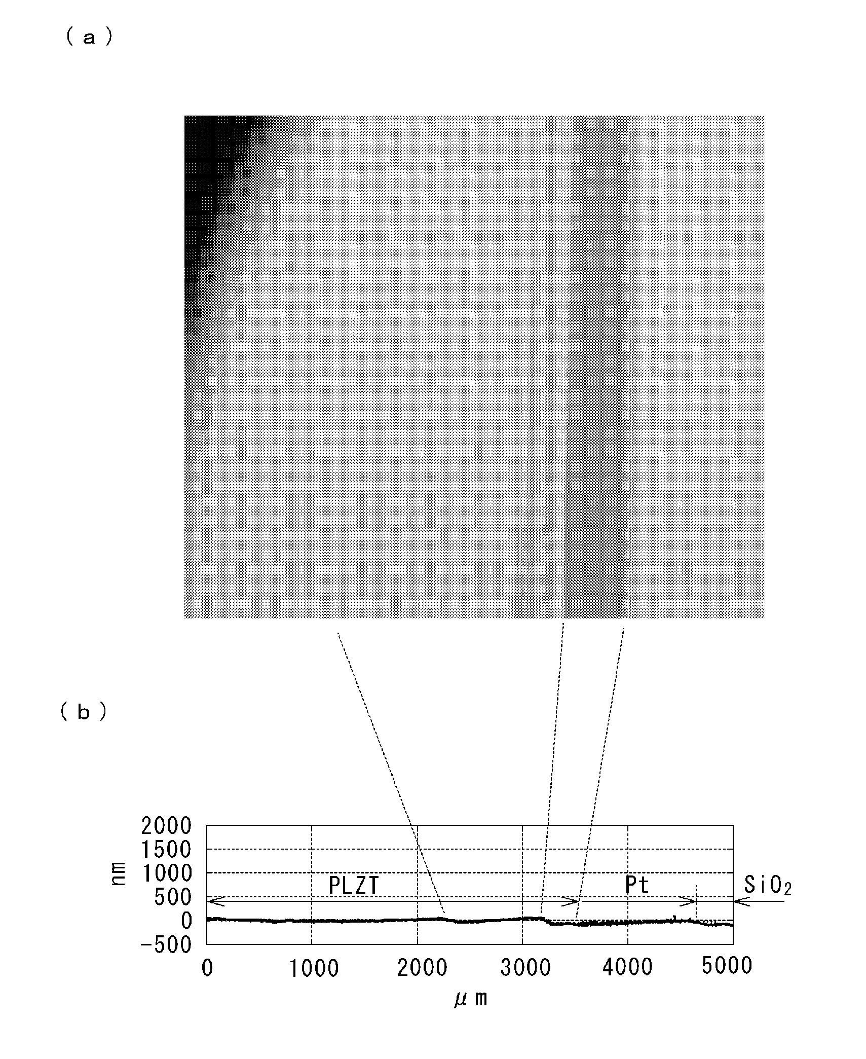
[0103] As Example 2, the situation of the layered perovskite oxide film containing Bi is the same as that of the perovskite oxide film containing Pb (Example 1), and the 10wt% raw material solution 2-1 of Table 2 ~2-6 spin-coated on 4 inch Pt / SiO 2 / Si substrate, in order to avoid cracks caused by the thicker film at the outer peripheral end of the substrate, while using a spin coater to rotate the substrate at 2500rpm, each of the removal liquids 1 to 62 shown in Table 5 and Table 6 was sprayed on the At a position 5 mm inward in the radial direction from the outer peripheral end of the substrate, the gel-like coating film was dissolved and EBR treatment was performed. This substrate was heated on a hot plate in the same manner as in the case of the Pb-containing perovskite-type oxide thin film to obtain a Bi-containing oxide thin film in a state where the outer peripheral end portion was etched. As in the case of the Pb-containing perovskite-type oxide thin film, this opera...


PUM


Abstract

A fluid for removing a coating film formed by CSD is sprayed or dropped onto the peripheral edge of a substrate to be subsequently heat-treated in a CSD method, the fluid comprising a mixture of one or more organic solvents and water in a weight ratio of 50 / 50 to 0 / 100, the organic solvents being selected from ss-diketones, ss-ketoesters, polyhydric alcohols, carboxylic acids, alkanolamines, a-hydroxycarboxylic acids, a-hydroxycarbonyl derivatives, and hydrazone derivatives. Thus, the coating film is partly removed without causing cracks or local peeling, and particle generation is prevented.

Description

technical field [0001] The present invention relates to a CSD method such as a sol-gel method in which a ferroelectric thin film such as a PZT film or an SBT film is formed by applying and firing a raw material solution to remove the outer peripheral edge of a coated film of a raw material solution. The solution for removing a CSD coating film of the present invention, a method for removing the peripheral edge of a coating film using the same, a ferroelectric thin film, and a method for producing the same. [0002] This application is based on Japanese Patent Application No. 2009-156064 filed on June 30, 2009, Japanese Patent Application No. 2009-165140 filed on July 13, 2009, and Japanese Patent Application No. 2010-16071 filed on January 27, 2010 Priority is claimed, the content of which is hereby cited. Background technique [0003] Ferroelectrics such as PZT (lead zirconate titanate) and SBT (strontium bismuth tantalate) have a perovskite crystal structure and are expec...

Claims


Application Information

Patent Timeline
IPC IPC(8): H01L21/306H01L21/316
CPCH01L21/02197H01L21/02087H01L21/02282
Inventor 曾山信幸渡边敏昭樱井英章
Owner MITSUBISHI MATERIALS CORP
Features
  • R&D
  • Intellectual Property
  • Life Sciences
  • Materials
  • Tech Scout
  • Unparalleled Data Quality
  • Higher Quality Content
  • 60% Fewer Hallucinations
Learn More