
Real-time dynamic proton imaging and radiotherapy image imaging method, image reconstruction optimization algorithm and imaging system using method

A proton imaging and image imaging technology, applied in the field of imaging, can solve the problems of poor image position resolution, inability to correct proton scattering, inability to optimize and improve resolution, etc.

Inactive Publication Date: 2012-06-13
浙江硅萃影像科技有限责任公司
View PDF4 Cites 9 Cited by
  • Summary
  • Abstract
  • Description
  • Claims
  • Application Information

AI Technical Summary

Problems solved by technology

The film method is complex and cannot be applied to real-time image acquisition and processing
The ionization chamber scanning method is currently widely used in clinical applications, and its defect is that the resolution of the image position is poor.
Moreover, the above-mentioned single-layer image system can only measure the position information of the protons after they are ejected from the object to be measured, so it cannot effectively correct the proton scattering and cannot optimize and improve the resolution.

Method used


Image

  • Real-time dynamic proton imaging and radiotherapy image imaging method, image reconstruction optimization algorithm and imaging system using method
  • Real-time dynamic proton imaging and radiotherapy image imaging method, image reconstruction optimization algorithm and imaging system using method
  • Real-time dynamic proton imaging and radiotherapy image imaging method, image reconstruction optimization algorithm and imaging system using method

Examples


Embodiment 1

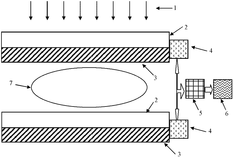
[0035] like figure 1 , figure 2 As shown, the imaging system using the real-time dynamic proton imaging and radiotherapy image imaging method described in this embodiment mainly includes a TFT amorphous silicon flat panel detector 3 with a cesium iodide coating 2 and an analog-to-digital converter 4. The system has two TFT amorphous silicon flat panel detectors 3 arranged at intervals, and a space for the detected object 7 is set between the two TFT amorphous silicon flat panel detectors 3, and the analog-to-digital converter 4 and the signal synchronization processor 5 Connected, the signal synchronization processor 5 is connected with the image system 6 again.

[0036] The image imaging method of real-time dynamic proton imaging and radiotherapy described in this embodiment collects the energy of proton rays through a TFT amorphous silicon flat panel detector with a cesium iodide coating, and then obtains an image through digital-to-analog conversion. The energy acquisiti...

Embodiment 2

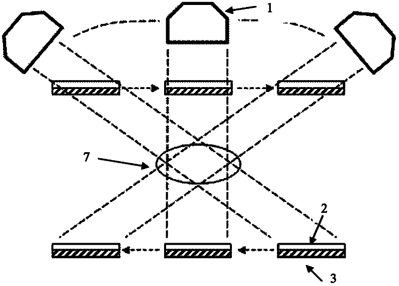
[0058] like figure 2 As shown, in the image imaging using real-time dynamic proton imaging and radiotherapy described in this embodiment, the movable proton ray source 1 and the TFT amorphous silicon flat panel detector 3 collect image information of the measured object 7 from different angles. Proton images from different angles (proton energy distribution map) can generate image information of different depth layers of the object to be measured through the image tomography system. Applied in the field of proton radiation therapy, it provides images and range information from the patient's body surface to the depth of the tumor to ensure and improve the quality of treatment.


PUM


Abstract

The invention relates to a real-time dynamic proton imaging and radiotherapy image imaging method. According to the method, the energy of proton rays is acquired by a thin film transistor (TFT) amorphous silicon flat panel detector with a cesium iodide coating and is subjected to digital-to-analog conversion to form an image. The method is characterized in that: the energy of the proton rays is acquired twice, one time is before the proton rays are transmitted into a detected object, and the other time is after the proton rays pass through the detected object; and data acquired through two-time acquisition is processed to form the image. The method has the characteristic that: by comparing a deviation value of the two-time acquired data, the influence of a phenomenon that the proton rays pass through the detected object and are scattered on imaging is reduced.

Description

technical field [0001] The invention relates to an imaging method, in particular to an image imaging method for real-time dynamic proton imaging and radiotherapy, an image reconstruction optimization algorithm and an imaging system using the method. Background technique [0002] Proton radiation therapy technology is a new method of cancer treatment. Because most of the energy is deposited on the Bragg peak, proton radiotherapy has significant treatment accuracy advantages compared with traditional photon therapy: high tumor irradiation dose; low radiation dose to the proximal tissue between the incident surface and the tumor; compared with the deep tumor No radiation dose to distal tissues. In order to ensure that the high precision of proton radiotherapy is transformed into high curative effect, it is necessary to monitor whether the two-dimensional distribution of proton beam energy meets the accuracy requirements of the treatment planning system in real time. As proton...

Claims


Application Information

Patent Timeline
Patent Type & Authority Applications(China)
IPC IPC(8): A61N5/00
Inventor 韩滨黄惠徐榭徐开文
Owner 浙江硅萃影像科技有限责任公司
Learn More