Self-aligning roller bearing split-type retainer and design method thereof
A self-aligning roller bearing and design method technology, applied in the field of bearings, can solve problems such as short life, large pocket machining error, and weak cage strength
- Summary
- Abstract
- Description
- Claims
- Application Information
AI Technical Summary
Problems solved by technology
Method used
Image

Examples
Embodiment 1
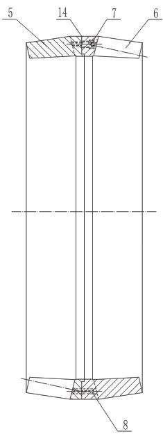
[0031]The number Z of the pockets on one side of the cage is an even number, which can be divisible by 2 but not by 4, that is, when the remainder is 2 after being divided by 4, the right half of the cage 6 is rotated 90° clockwise or counterclockwise, and the axial direction is staggered Cut out 15, align the center of the beam 9 of the right half 6 of the cage with the center of the pocket 10 of the left half 5 of the cage, clamp and fix the left half 5 and right half 6 of the cage, and drill connection hole. The connection hole is located at the off-center position at the bottom of the pocket hole of the cage. The connection hole is composed of 8 counterbores 13, threaded holes 12, and at least 4 pin holes 11. Among them, 8 threaded holes 12 and 8 counterbores 13 are matched and drilled with 8 7 inner hexagon screws are connected, 8 pairs of connecting holes are located near the axial section 15 and reconnected after staggering, 8 counterbores 13 are located on the right ha...
Embodiment 2
[0033] When the number of pockets on one side of the cage can be divisible by 4, the left half 5 and right half 6 of the cage are cut symmetrically along the central axis of the pockets, and the right half of the cage is rotated 90°± clockwise or counterclockwise (180° / Z), stagger the axial section 15, make the center of the beam 9 of the right half 6 of the cage align with the center of the pocket 10 of the left half 5 of the cage, and drill the connection hole. The rest of the installation process is the same as in Embodiment 1.
Embodiment 3
[0035] The number Z of the pockets on one side of the cage is an odd number, and when the remainder is 1 after being divided by 4, the left half 5 and the right half 6 of the cage are cut axially along the center of the pockets, and the cut positions are separated by 180°± (180° / Z), the right half of the cage rotates 90°+(90° / Z) clockwise or counterclockwise, staggers the axial cut 15, and aligns the center of the beam 9 of the right half of the cage 6 The center of the pocket hole 10 of cage left half part 5 is equipped with drilling connecting holes. The rest of the installation process is the same as in Embodiment 1.
PUM
 Abstract
Description
Claims
Application Information
 - R&D
- Intellectual Property
- Life Sciences
- Materials
- Tech Scout
- Unparalleled Data Quality
- Higher Quality Content
- 60% Fewer Hallucinations
Browse by: Latest US Patents, China's latest patents, Technical Efficacy Thesaurus, Application Domain, Technology Topic, Popular Technical Reports.
© 2025 PatSnap. All rights reserved.Legal|Privacy policy|Modern Slavery Act Transparency Statement|Sitemap|About US| Contact US: help@patsnap.com