
Overlay welding process for deep holes on valve body sealing surface

A technology of sealing surface and valve body, which is applied in the field of deep hole surfacing welding technology of valve body sealing surface, can solve the problems of deterioration of tissue performance around the sealing surface, unguaranteed execution process, unstable welding quality, etc., so as to ensure the sealing performance, Improve welding conditions and save welding rods

Inactive Publication Date: 2012-06-27
NANTONG POWER STATION VALVE
View PDF4 Cites 12 Cited by
  • Summary
  • Abstract
  • Description
  • Claims
  • Application Information

AI Technical Summary

Problems solved by technology

In addition, since most of the domestic valve body manufacturers currently use manual welding in the surfacing welding process, the hole is full of smoke during deep hole welding, the visibility is poor, and the welding rod must be lengthened. The operation depends entirely on the welder's personal feeling. The execution process cannot be guaranteed at all, so the welding quality is unstable and the quality fluctuates greatly, resulting in a low product qualification rate
Multiple repair welding is required, which not only greatly increases the production cost, but also prolongs the production cycle. Multiple repair welding will inevitably lead to deterioration of the performance of the tissue around the sealing surface, which will not only affect the service life, but also leave hidden safety hazards

Method used


Image

  • Overlay welding process for deep holes on valve body sealing surface
  • Overlay welding process for deep holes on valve body sealing surface
  • Overlay welding process for deep holes on valve body sealing surface

Examples


Embodiment Construction

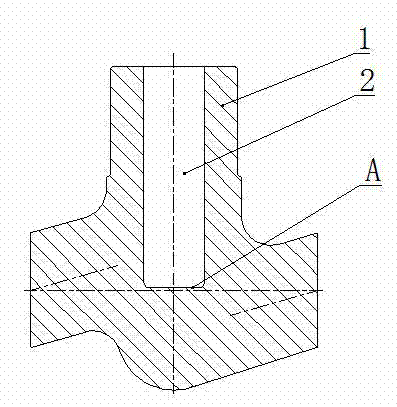
[0017] The specific steps are: First drill the center hole of the valve body :Such as figure 2 As shown, drill a valve body middle hole 2 extending from the valve stem hole position of the valve body to the valve body sealing surface A on the valve body blank 1, the valve body middle hole 2 is a blind hole, and the valve body middle hole 2 The aperture size requires a certain margin for subsequent machining.

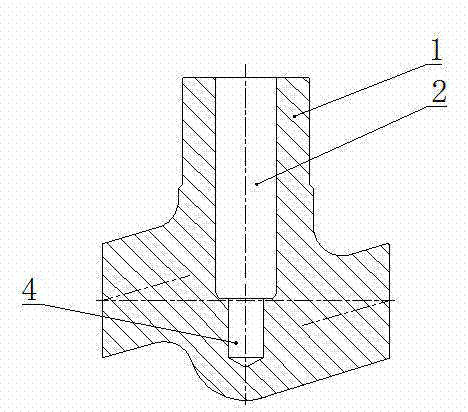
[0018] Then drill the craft hole :Such as image 3 As shown, a process hole 4 with a concentric diameter smaller than the valve body center hole 2 is drilled at the sealing surface A at the bottom of the valve body middle hole 2 of the valve body blank 1. The diameter of the process hole 4 ensures that the welding area reaches the sealing surface surfacing The processing width and the requirement to leave a certain margin for subsequent machining.

[0019] Set up smoke exhaust structure :Such as Figure 4 As shown, a smoke exhaust hole 5 communicating with the ...


PUM


Abstract

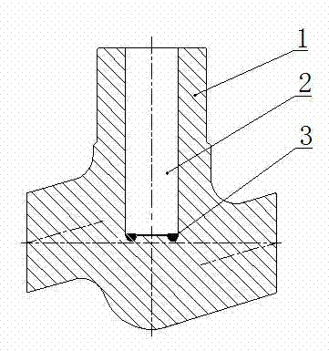
The invention relates to an overlay welding process for deep holes on a valve body sealing surface. The innovation point of the overlay welding process is that the steps are as follows: drilling out a valve body middle hole extending to the valve body sealing surface from the position of a valve rod hole of the valve body on valve body blank; drilling out concentric process holes, diameter of which is smaller than that of the valve body middle hole, on the bottom part of the valve body middle hole of the valve body blank; carrying out overlay welding of hard alloy on a shaft shoulder surface between the process holes and the valve body middle hole; carrying out thermal treatment to the valve body blank; and finally, machining the sealing surface of the valve body blank; the bottom part of the valve body middle hole is drilled with process holes, so that the hole diameter of the process holes ensures that the welding area achieves the processing width of the overlay welding on the sealing surface; overlay welding is carried out to the annular shaft shoulder surface between the process holes and the valve body middle hole, so that compound stress is reduced to be within a safe range to avoid crackles. The inner wall of the overlay welding layer does not contact with the mother material, so that fusion phenomenon does not exist, and the hardness of the overlay welding layer is ensured, and the sealing performance is ensured. Besides, overlay welding materials on the positions of the process holes are saved, so that welding rods are saved.

Description

technical field [0001] The invention relates to a deep hole surfacing process for the sealing surface of a valve body, in particular to a process for artificially surfacing deep holes on the sealing surface by using F92 heat-resistant steel as the valve body. Background technique [0002] Globe valve is the most widely used valve, which is used to connect or cut off the medium in the pipeline. Its valve body has an annular sealing surface, which can cooperate with the sealing surface of the valve core to realize the cutting or conducting of the pipeline medium. With the continuous development of my country's thermal power industry, more and more supercritical and ultra-supercritical units are used. F92 heat-resistant steel plays an important role in these units due to its excellent performance advantages. The F92 heat-resistant steel material has been used in my country for a short time, and there are no relevant standards and specifications in China, while the relevant for...

Claims


Application Information

Patent Timeline
IPC IPC(8): F16K27/00C21D9/50
Inventor 夏明民尤广泉刘海峰黄祥
Owner NANTONG POWER STATION VALVE
Learn More