
Flue gas spraying, purifying and heat recovering system for coal burning boiler

A coal-fired boiler and heat recovery technology, applied in water heaters, fluid heaters, lighting and heating equipment, etc., can solve problems such as high exhaust gas temperature, environmental pollution, and waste of heat energy

Inactive Publication Date: 2012-06-27
ENG DESIGN & RES INST OF GENERAL ARMAMENTS DEPT
View PDF11 Cites 13 Cited by
  • Summary
  • Abstract
  • Description
  • Claims
  • Application Information

AI Technical Summary

Problems solved by technology

High-temperature flue gas emission not only causes a lot of waste of heat energy, but also pollutes the environment. Therefore, economizers, dust collectors and other equipment are generally added to reduce the exhaust gas temperature below 200°C, and the smoke and dust emissions fall within the emission standards.
However, the exhaust gas temperature after the economizer still has usable value, and there is still room for reducing the smoke and dust emissions
Moreover, the exhaust gas temperature is too high, which also causes the thermal efficiency of the boiler to decrease.

Method used


Image

  • Flue gas spraying, purifying and heat recovering system for coal burning boiler
  • Flue gas spraying, purifying and heat recovering system for coal burning boiler

Examples


Embodiment Construction

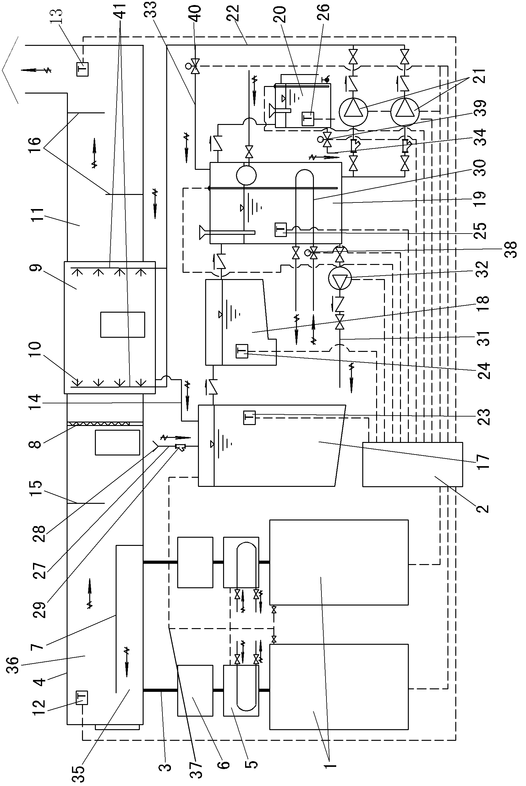
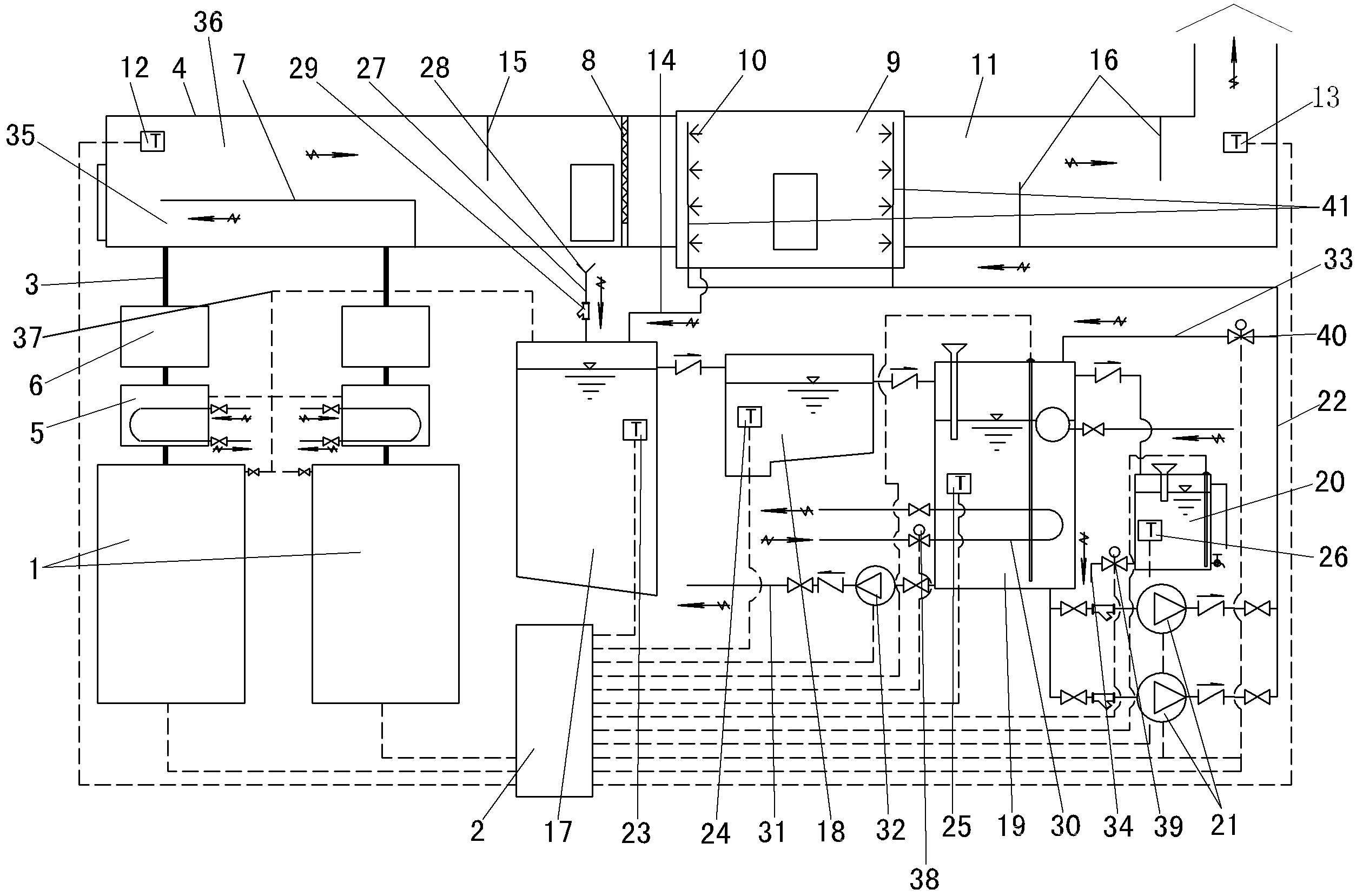
[0015] like figure 1 As shown, the coal-fired boiler flue gas spray purification and heat recovery system of the present invention includes a control system 2 for controlling the operation of two coal-fired boilers 1, and a labyrinth-type soot settling chamber connected to the exhaust ducts 3 of the two coal-fired boilers 1 4.

[0016] The two exhaust ducts 3 are lined with acid-proof cement, and the two exhaust ducts 3 are connected with a waste heat recovery device 5 and a dust collector 6 .

[0017] The inner cavity of the labyrinth dust settling chamber 4 is processed with a partition 7 that divides it into a first return flue 35 and a second return flue 36 . The first return flue 35 communicates with the second return flue 36 , and the two exhaust ducts 3 communicate with the first return flue 35 respectively. Several first flue gas deflectors 15 are processed on the inner cavity wall of the second return flue 36 . A smoke filter screen 8 is vertically installed on the...


PUM


Abstract

The invention discloses a flue gas spraying, purifying and heat recovering system for a coal burning boiler and belongs to the field of flue gas treatment or waste gas device configuration. The flue gas spraying, purifying and heat recovering system comprises a control system and the like; a separation board by which an inner cavity of a soot settling chamber is divided into two return flues is arranged in the inner cavity of the soot settling chamber; a smoke exhaust channel is communicated with the return flues; a waste heat receiving device and a dust remover are connected onto the smoke exhaust channel; a soot filter screen is arranged at the right part of a right cavity of a labyrinth type soot settling chamber; the right end of the soot settling chamber is communicated with a spraying chamber; the right end of the spraying chamber is communicated with a labyrinth type extended cooling channel; the labyrinth type extended cooling channel is communicated with a chimney; temperature controllers connected with the control system are respectively arranged in the soot settling chamber and an inner cavity of the labyrinth type extended cooling channel; the spraying chamber is connected with a water treatment system through a plurality of recovering water pipes; a plurality of water inlet pipes extend into the inner cavity of the spraying chamber; and spraying nozzles are arranged on the water inlet pipes. The flue gas spraying, purifying and heat recovering system disclosed by the invention is simple and convenient to manage; and according to the flue gas spraying, purifying and heat recovering system, emission heat of the coal burning boiler can be safely and reliably absorbed; thermal pollution, pollution from dust in the soot, pollution from sulfide, nitride and the like are reduced and flue gas is enabled to achieve non-hazardous emission.

Description

technical field [0001] The invention relates to the technical field of configuration of flue gas or waste gas treatment devices, in particular to a coal-fired boiler flue gas spray purification and heat recovery system. Background technique [0002] my country's energy structure is still dominated by polluting energy—coal. The pollution of coal-fired boilers, in addition to coal transportation, ash pollution to roads and surrounding pollution of storage sites, and fly ash pollution, flue gas emission is the biggest pollution. In the design and manufacture of general industrial coal-fired boilers, in order to avoid corrosion of the heating surface at the rear and ash blockage, and to further burn out fly ash, the exhaust gas temperature in the standard state is generally not lower than 180°C, and the highest can reach 250°C. High-temperature flue gas emission not only causes a lot of waste of heat energy, but also pollutes the environment. Therefore, economizers, dust collec...

Claims


Application Information

Patent Timeline
Patent Type & Authority Applications(China)
IPC IPC(8): F23J15/04F24H1/00B01D50/00
Inventor 张清张振东朱蓉侯军祥温庆林江红斌张晓航张肃廷任建平宋立池媛刘长林
Owner ENG DESIGN & RES INST OF GENERAL ARMAMENTS DEPT
Learn More