Solid fuel drying equipment

A technology of solid fuel and drying gas, which is applied in the directions of drying solid materials, heating to dry solid materials, and drying gas arrangement. Effects of contact time, ease of particle backmixing, and reduced bed pressure drop

Active Publication Date: 2012-06-27
WISON ENG
View PDF14 Cites 11 Cited by
  • Summary
  • Abstract
  • Description
  • Claims
  • Application Information

AI Technical Summary

Problems solved by technology

The advantage of this method is that the thermal efficiency of the system is high, and the dried water can be recycled, but the disadvantage is that for a fluidized bed with a relatively large material holding capacity, the pressure drop through the bed is relatively large, and the fan pressure required to maintain the fluidization The head is high, the power consumption is large, and the arrangement of the built-in heat exchanger is complicated

Method used


Image

  • Solid fuel drying equipment
  • Solid fuel drying equipment
  • Solid fuel drying equipment

Examples


Embodiment 1

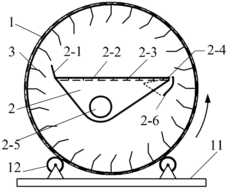
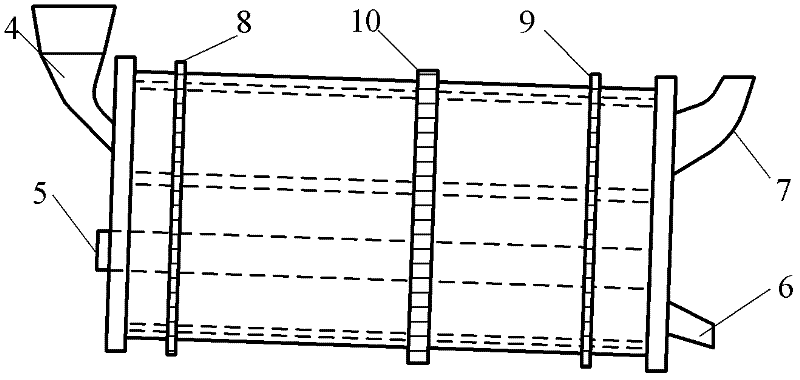
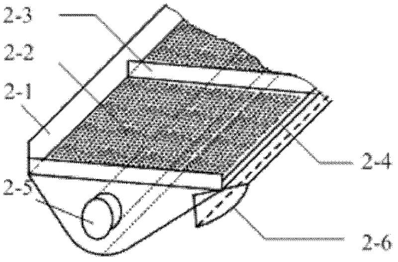
[0024] Such as figure 1 and figure 2 The rotary fluidized bed shown is mainly composed of a rotary drum 1 and a fluidized bed 2 . The inner wall of the drum 1 is provided with a lifting board 3 with a fixed knuckle angle of 120°, which is used to repeatedly transfer the lignite particles falling to the bottom of the drum to the fluidized bed. One end (inclined high end) of the drum is provided with a material inlet 4 and an air inlet 5, and the other end is provided with a material outlet 6 and an air outlet 7. The rotating drum shell is welded with transmission gears: driven gear 8, driven gear 9, driving gear 10, wherein driven gear 8 and driven gear 9 are connected with gear 12 fixed on the base plate 11. The driving gear 10 is connected with the transmission gear (not shown) of the motor system to drive the drum 1 to rotate at a certain speed. Rotating cylinder 1 is placed obliquely, and the inclination angle is 8°, and the inclination angle of rotating cylinder 1 can ...

Embodiment 2

[0027] The rotary drum is placed obliquely, the inclination angle of the rotary drum is 10°, the folded flight board on the inner wall of the drum is a movable folding angle, and the folding angle of the folded flight board is 90°, and the fluidized bed is set at intervals of 30cm along the axis of the drum. Partition, the height of the partition is 5cm, a baffle with a height of 100cm is set at one end of the fluidized bed, and the inclination angle of the baffle is 160°, and an overflow weir is provided at the other end of the fluidized bed, and the height of the overflow weir is 5cm , the temperature of the drying gas is 120°C. All the other are with embodiment 1.

Embodiment 3

[0029] The rotary drum is placed obliquely, the inclination angle of the rotary drum is 5°, the folded flight board on the inner wall of the drum is a fixed folding angle, and the folding angle of the folded flight board is 180°, and the fluidized bed is set at intervals of 150cm along the axis of the drum. Partition, the height of the partition is 30cm, a baffle with a height of 80cm is set at one end of the fluidized bed, the inclination angle of the baffle is 90°, and an overflow weir is provided at the other end of the fluidized bed, and the height of the overflow weir is 30cm , the temperature of the drying gas is 250°C. All the other are with embodiment 1.


PUM


Abstract

The invention relates to solid fuel drying equipment, which comprises a drum, a fluidized bed, a fan and a dust removing filter. A bent lifting plate is arranged on the inner wall of the drum, the fluidized bed is mounted in the drum, the fan is connected with the drum, dry air flowing through the fan is filled into the drum via the fluidized bed to realize primary classification for grains falling on the fluidized bed, larger moisture grains are dried on the fluidized bed and in the drum when falling, and smaller fine powdery grains are carried by air to pass through the drum, are dried when carried by the air and are collected by the dust removing filter to be used as dry products. Compared with the prior art, the solid fuel drying equipment has the advantages of simplicity in operation, easiness in control, high drying capacity and the like.

Description

technical field [0001] The invention relates to a device for drying solid fuel, in particular to a device for drying low-rank coal such as lignite by combining equipment such as a rotating cylinder, a fluidized bed, a fan, and a dust removal device. Background technique [0002] China is rich in coal but poor in oil and gas. Coal resources have always played an irreplaceable role in my country's energy structure and utilization. Among them, lignite, as a low-rank coal, accounts for 13% of my country's total coal reserves, reaching 130 billion tons. Since lignite is a kind of coal with high volatile content, high moisture and low calorific value, it is often necessary to improve its quality and economical efficiency through drying and upgrading. [0003] Conventional lignite drying methods include drum dryers that use hot flue gas for direct heating (such as patent application No. 200810241001.X) and indirect heating drum dryers that use heat exchange tubes (such as patent a...

Claims


Application Information

Patent Timeline
Patent Type & Authority Applications(China)
IPC IPC(8): F26B11/06F26B3/08F26B21/00F26B25/00
Inventor 刘兵田靖
Owner WISON ENG
Why Eureka
Try Eureka