Thermal fatigue performance test and analysis method for metal matrix composite material

A composite material and thermal fatigue technology, applied in the direction of analyzing materials, measuring devices, strength characteristics, etc., can solve problems such as failure to consider crack shape, distribution, inaccurate results, large errors, etc., to reduce thermal fatigue failure, operation Simple, error-free effect

Inactive Publication Date: 2012-06-27
KUNMING UNIV OF SCI & TECH
View PDF2 Cites 2 Cited by
  • Summary
  • Abstract
  • Description
  • Claims
  • Application Information

AI Technical Summary

Problems solved by technology

[0003] At present, there is no precedent for evaluating and analyzing the thermal fatigue performance of metal matrix composites. The evaluation of thermal fatigue performance is only limited to hot work die steel, but the results are not accurate, and the errors caused by humans are relatively large, and The thermal fatigue performance test and analysis method of hot work die steel is too narrow, without considering the shape and distribution of cracks and other factors. Test and Analysis of Thermal Fatigue Properties of Composite Materials

Method used


Image

  • Thermal fatigue performance test and analysis method for metal matrix composite material
  • Thermal fatigue performance test and analysis method for metal matrix composite material
  • Thermal fatigue performance test and analysis method for metal matrix composite material

Examples


Embodiment 1

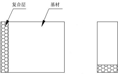
[0022] (1) Cut the Cr15 high-chromium steel-based composite material sample with a volume fraction of tungsten carbide of 20% and a volume fraction of high-carbon ferrochrome powder of 80% into squares, and grind the side with the base material and the composite layer to Polished state;

[0023] (2) Heat the sample obtained in step (1) at a temperature of 600°C for 10 minutes until the sample is fully heated;

[0024] (3) Put the high-temperature sample obtained in step (2) into water at room temperature, and make it chill to room temperature, so as to simulate the working conditions of chilling and chilling;

[0025] (4) Polish the sample cooled in step (3) to remove the surface oxide skin, observe the grinding surface in step (1) with a metallographic microscope, and take pictures of cracks and composite layers;

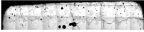
[0026] (5) Repeat steps (2), (3) and (4) 30 times, and take photos (such as image 3 As shown) use the thermal fatigue crack image analysis system to conduct qua...

Embodiment 2

[0029] (1) Cut the Cr15 high-chromium steel-based composite material sample with a volume fraction of tungsten carbide of 40% and a volume fraction of high-carbon ferrochrome powder of 60% into squares, and grind the side with the base material and the composite layer to Polished state;

[0030] (2) Heat the sample obtained in step (1) at a temperature of 800°C for 5 minutes until the sample is fully heated;

[0031] (3) Put the high-temperature sample obtained in step (2) into water at room temperature, and make it chill to room temperature, so as to simulate the working conditions of chilling and chilling;

[0032] (4) Polish the sample cooled in step (3) to remove the surface oxide skin, observe the grinding surface in step (1) with a metallographic microscope, and take pictures of cracks and composite layers;

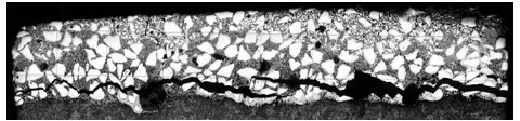
[0033] (5) Repeat steps (2), (3) and (4) 36 times to take the photos (such as Figure 4 Shown) Quantitative analysis of cracks with the thermal fatigue crack imag...

Embodiment 3

[0036] (1) Cut the Cr15 high-chromium steel-based composite material sample with a volume fraction of tungsten carbide of 40% and a volume fraction of high-carbon ferrochrome powder of 60% into squares, and grind the side with the base material and the composite layer to Polished state;

[0037] (2) Heat the sample obtained in step (1) at a temperature of 500°C for 8 minutes until the sample is fully heated;

[0038] (3) Put the high-temperature sample obtained in step (2) into water at room temperature, and make it chill to room temperature, so as to simulate the working conditions of chilling and chilling;

[0039] (4) Polish the sample cooled in step (3) to remove the surface oxide skin, observe the grinding surface in step (1) with a metallographic microscope, and take pictures of cracks and composite layers;

[0040] (5) Repeat steps (2), (3) and (4) 40 times, and use the thermal fatigue crack image analysis system to conduct quantitative analysis of the cracks in the ph...


PUM


Abstract

The invention provides a thermal fatigue performance test and analysis method for a metal matrix composite material. According to the method, a metal matrix composite material specimen is cut into cubic blocks, and the surface with the matrix and the composite layer is grinded into the polishing state; a heat treatment is performed until the specimen is completely heated and the temperature is increased; the heated specimen is placed in water with a room temperature, such that the specimen is chilled to the room temperature; a polishing treatment is performed, a metallographic microscope is adopted to observe the grinded surface, and the crack and the composite layer are photographed; treatments of heating, cooling and observing are repeatedly performed a plurality of times, the photographed pictures are subjected to quantitative crack analysis by using a thermal fatigue crack image analysis system, wherein the thermal fatigue failure mechanism, the manners of the thermal fatigue crack initiation and the thermal fatigue crack expansion can be analyzed so as to achieve the thermal fatigue performance test and analysis of the metal matrix composite material. According to the present invention, the method of the present invention has characteristics of simple operation, and strong controllability; the crack distribution, the crack shape and other factors of various fields are comprehensively considered, such that the result is close to the actual result.

Description

technical field [0001] The invention relates to a method for testing and analyzing thermal fatigue performance of metal matrix composite materials, belonging to the field of performance testing and analysis of metal matrix composite materials. Background technique [0002] Thermal fatigue failure refers to the phenomenon that metal matrix composites will form reticular cracks near the macroscopic interface between the composite layer and the base metal and inside the composite layer under the alternating action of shock and heat cycles. One of the main forms of service failure under cold and hot conditions. [0003] At present, there is no precedent for evaluating and analyzing the thermal fatigue performance of metal matrix composites. The evaluation of thermal fatigue performance is only limited to hot work die steel, but the results are not accurate, and the errors caused by humans are relatively large, and The range considered in the thermal fatigue performance test and...

Claims


Application Information

Patent Timeline
Patent Type & Authority Applications(China)
IPC IPC(8): G01N3/60
Inventor 蒋业华隋育栋李祖来黄汝清周荣山泉
Owner KUNMING UNIV OF SCI & TECH
Why Eureka
Try Eureka