Radio-frequency discharge ionization device enhanced by using photoelectric effect

A technology of radio frequency discharge and photoelectric effect, applied in discharge tubes, circuits, electrical components, etc., can solve the problems of unstable discharge, difficulty in starting radio frequency discharge, narrow working pressure range of radio frequency discharge, etc. The effect of increasing the working air pressure range

Active Publication Date: 2015-01-07
KUSN HEXIN MASS PECTRUM TECH
View PDF5 Cites 0 Cited by
  • Summary
  • Abstract
  • Description
  • Claims
  • Application Information

AI Technical Summary

Problems solved by technology

The technical problem to be solved by the present invention is that the working air pressure range of the radio frequency discharge is narrow in the current technology, the radio frequency discharge is difficult to start and the discharge is unstable.

Method used


Image

  • Radio-frequency discharge ionization device enhanced by using photoelectric effect

Examples


Embodiment 1

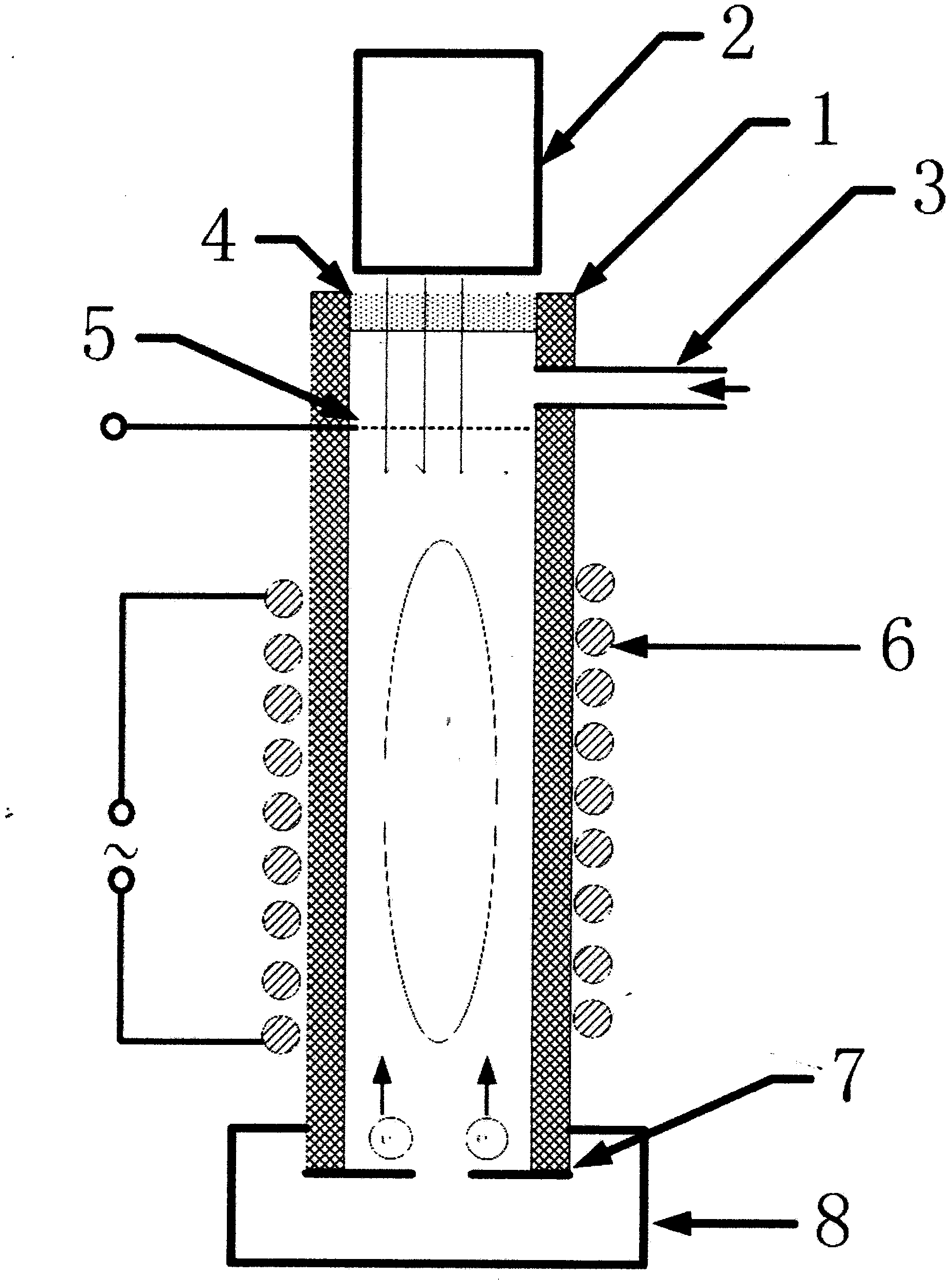
[0019] Example 1, see figure 1 Shown:

[0020] The present invention is a radio frequency discharge ionization device enhanced by the photoelectric effect, comprising an insulating medium cavity 1, an ultraviolet light source 2, a gas inlet 3, an optical lens 4, a grid 5, a radio frequency coil 6 and a photoelectric conversion electrode 7, the insulating medium cavity 1 Both ends are open, and the lower port is connected to the photoelectric conversion electrode 7; the optical lens 4 is installed at the upper port of the insulating medium cavity 1 and sealed; the radio frequency coil 6 is sleeved in the insulating medium cavity 1 Periphery of the middle part; the insulating medium cavity 1 is provided with the gas inlet 3 and the grid 5 in sequence between the optical lens 4 and the radio frequency coil 6; the ultraviolet light source 2 is arranged on the front of the optical lens 4 above.

[0021] The material of the insulating medium cavity 1 is quartz, the inner diameter ...

Embodiment 2

[0023] Example 2, see figure 1 Shown:

[0024] The structure of this embodiment is basically the same as that of Embodiment 1. The material of the insulating medium cavity 1 is glass, the inner diameter is 1mm, and the length is 20mm; the working gas is argon, and the gas flow rate is 1mL / min; the ultraviolet light source 2 is capable of emitting A light source with a wavelength less than 400nm; the aperture of the gas inlet 3 is 0.1 mm, 1 mm apart from the radio frequency coil and the optical lens; the material of the optical lens 4 is quartz, and its structural shape is a concave lens; The power supply applies a positive voltage, which is nickel material, and the hole density is 200 mesh; the radio frequency coil 6 is powered by a radio frequency power supply, the power frequency is 1MHz, the power is 0.05W, and it is cooled by air cooling or water cooling; the photoelectric conversion electrode 7 is a power The function is smaller than the photon energy in the ultraviolet ...

Embodiment 3

[0025] Example 3, see figure 1 Shown:

[0026] The structure of this embodiment is basically the same as that of Embodiment 1. The material of the insulating medium cavity 1 is ceramics, the inner diameter is 9mm, and the length is 200mm; the working gas is argon, and the gas flow rate is 50mL / min; the ultraviolet light source 2 is capable of emitting A light source with a wavelength less than 400nm; the aperture of the gas inlet 3 is 10mm, 3mm apart from the radio frequency coil and the optical lens; the material of the optical lens 4 is magnesium fluoride, and its structural shape is a plane mirror; The positive voltage is applied by an external power supply, which is made of gold or aluminum, and the hole density is 10 meshes; the radio frequency coil 6 is powered by a radio frequency power supply, the power frequency is 50MHz, the power is 50W, and it is cooled by air cooling or water cooling; the photoelectric conversion electrode 7 It is a stainless steel electrode with...


PUM


Abstract

The invention relates to an ionization device, in particular to a radio-frequency discharge ionization device enhanced by using a photoelectric effect, which comprises an insulation medium cavity, an ultraviolet light source, a gas inlet, an optical lens, a grid mesh, a radio frequency coil and a photoelectric conversion electrode, wherein two ends of the insulation medium cavity are provided with openings, the lower opening is connected with the photoelectric conversion electrode; the optical lens is arranged at the upper opening of the insulation medium cavity and is sealed; the radio frequency coil is sleeved on the periphery of the middle of the insulation medium cavity; the insulation medium cavity is sequentially provided with the gas inlet and the grid mesh between the optical lens and the radio frequency coil; and the ultraviolet light source is arranged just above the optical lens. According to the radio-frequency discharge ionization device enhanced by using the photoelectric effect, radio frequency discharge is more easily started, and working air pressure range, ion leading-out efficiency and discharge stability of radio frequency discharge are improved.

Description

technical field [0001] The invention relates to an ionization device, in particular to a radio frequency discharge ionization device enhanced by photoelectric effect. Background technique [0002] Plasma technology has developed rapidly in recent years and has been widely used. For example, it can be used for: silicon wafer cleaning in the microelectronics industry, replacing the current acid or deionized water cleaning; cleaning all biochemically contaminated surfaces, including those contaminated by biochemical weapons Surface and space; instead of wet chemical method, it can be used for in-situ disinfection in the pharmaceutical and food industries; disinfection during medical treatment and treatment of skin diseases; cleaning of radioactive material surfaces; modified textile materials; modified material surfaces; ionization sources in mass spectrometry, etc. [0003] Chinese patent CN200710017858.9 discloses a water-cooled RF inductively coupled plasma discharge device,...

Claims


Application Information

Patent Timeline
Patent Type & Authority Patents(China)
IPC IPC(8): H01J37/32
Inventor 吴庆浩程平黄正旭高伟董俊国周振傅忠
Owner KUSN HEXIN MASS PECTRUM TECH
Why Eureka
Try Eureka