Method and device for dehydrating green coke by utilizing low-temperature flue gas of calcination system

A low-temperature flue gas and calcination technology, which is applied in the directions of dry gas arrangement, carbon preparation/purification, process efficiency improvement, etc., can solve the problem that the dehydration tank and the large-inclination belt conveyor occupy a large area and the waste heat of low-temperature flue gas is not utilized , large civil engineering foundation and other issues, to achieve the effect of reducing the risk of blasting into the kiln, saving construction funds, and reducing water content

Inactive Publication Date: 2012-07-04
SINOSTEEL ANSHAN RES INST OF THERMO ENERGY CO LTD
View PDF4 Cites 7 Cited by
  • Summary
  • Abstract
  • Description
  • Claims
  • Application Information

AI Technical Summary

Problems solved by technology

However, the dehydration tank and the large-inclination belt conveyor occupy a large area, and there is no redundant space in the established factory. Moreover, the construction of the dehydration tank requires a large civil engineering foundation, which requires a large investment.
However, the temperature of the low-temperature flue gas at the outlet of the waste heat boiler economizer in the original calcination system is above 180°C. Currently, it is directly purified by the dust removal and desulfurization integrated device and discharged into the atmosphere through the chimney. The waste heat of the low-temperature flue gas has not been utilized.

Method used


Image

  • Method and device for dehydrating green coke by utilizing low-temperature flue gas of calcination system
  • Method and device for dehydrating green coke by utilizing low-temperature flue gas of calcination system

Examples


Embodiment Construction

[0015] The specific embodiment of the present invention will be further described below in conjunction with accompanying drawing:

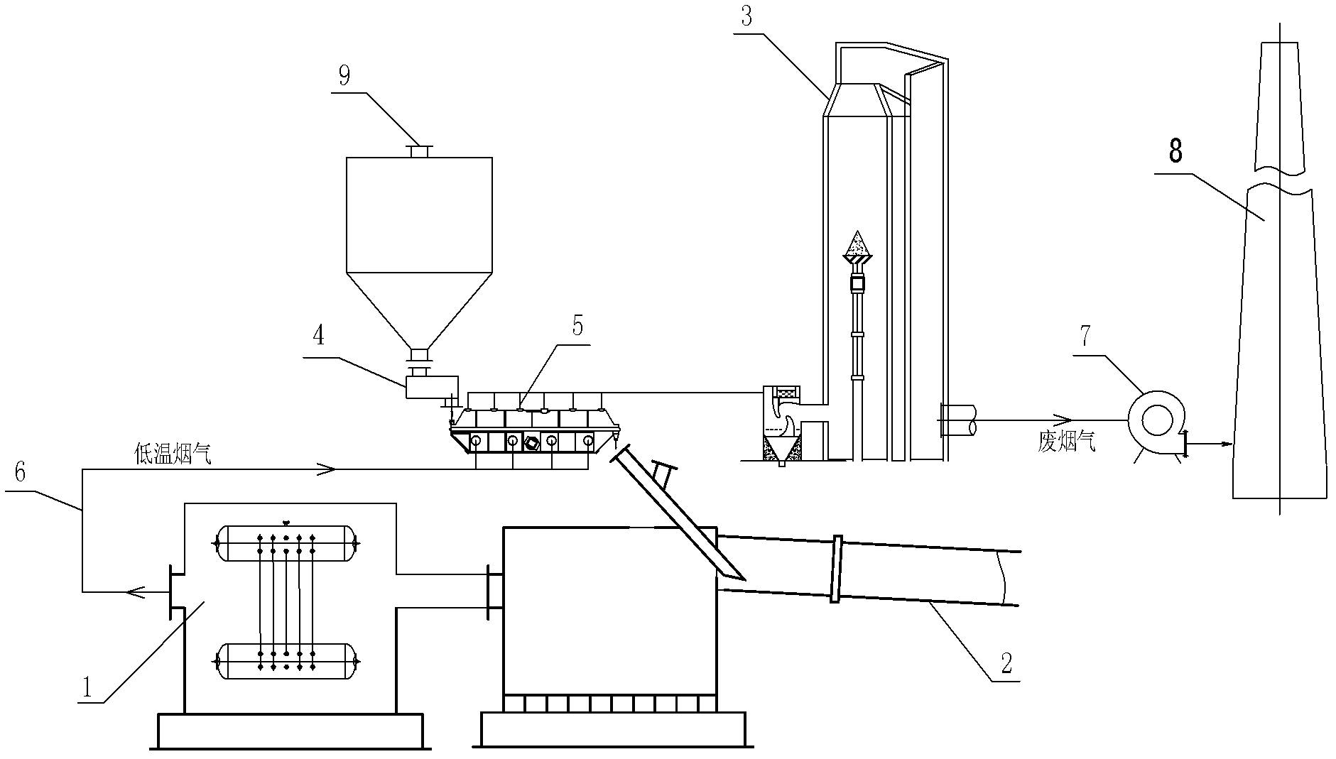
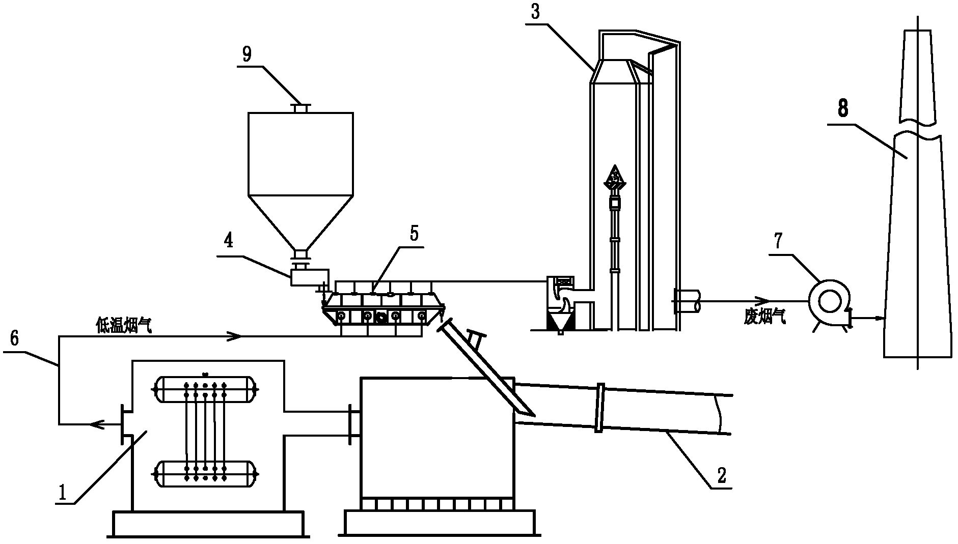
[0016] See figure 1 , is a structural schematic diagram of an embodiment of a device for dehydrating green coke by using low-temperature flue gas from a calcination system in the present invention. The original calcination system includes a waste heat boiler 1, a rotary kiln 2, an integrated device for dust removal and desulfurization 3, and a quantitative feeder 4. In order to reduce the water content of raw coke entering the kiln, a dryer 5 is installed between the quantitative feeder 4 and the rotary kiln 2. The green coke in the pre-calcination bin 9 enters the dryer 5 through the quantitative feeder 4 for dehydration and then enters the rotary kiln 2 for calcination. , the economizer outlet of the waste heat boiler 1 is connected to the air inlet of the dryer 5 through a pipeline 6, and the flue gas outlet of the dryer 5 is connected to the a...


PUM


Abstract

The invention relates to the field of utilizing residual heat of a calcination system of a rotary kiln, in particular to a method and a device for dehydrating green coke by utilizing low-temperature flue gas of the calcination system. The method and the device are characterized in that the low-temperature flue gas of residual-heat boiler of the calcination system is guided to a dryer through a pipeline and directly exchanged heat with the green coke, and the partial moisture contained in the green coke is vaporized and discharged after being dedusted and desulfured along with the flue gas through a dedusting desulfuration integrated device to ensure that the moisture content of the green coke entering into the kiln is reduced, wherein the sulphur content of the green coke is lower than 0.2%; the low-temperature flue gas is the back outlet flue gas of an economizer of the residual-heat boiler and the temperature of the flue gas is above 180 DEG C; and the temperature of the outlet flue gas of the dryer is no less than 110 DEG C. Compared with the prior art, the method and the device, disclosed by the invention, have the beneficial effects that: (1) the green coke dehydration rate is up to more than 2% to ensure that the calcination production is stabilized and the risk of the green coke being exploded and shattered when entering into the kiln is reduced in the meantime; (2) the fuel consumption is reduced by utilizing the residual heat of the calcination system per se; and (3) no big transformation is needed to on original process equipment to ensure that the construction fund is saved.

Description

technical field [0001] The invention relates to the field of waste heat utilization of a rotary kiln calcination system in the carbon and chemical industry, in particular to a method and a device for dehydrating raw coke by using low-temperature flue gas of the calcination system. Background technique [0002] The current coal-based, oil-based needle coke or petroleum coke are produced from different raw materials through a delayed coking process. The coke produced by delayed coking is traditionally called green coke, and after being calcined in a rotary kiln, it is called calcined coke. The raw coke in the delayed coking tower is crushed by hydraulic decoking equipment and discharged to the coke pit. At this time, the water content is 15-20%, and then it is transported to the transfer station for dehydration. At the transfer station, it is necessary to use the grab crane to turn the raw coke and move the position to reduce the moisture in the middle and lower layers of the ...

Claims


Application Information

Patent Timeline
Patent Type & Authority Applications(China)
IPC IPC(8): C01B31/02F27D17/00F26B21/14C01B32/05
CPCY02P10/25
Inventor 周建文屈滨刘长明孙刚
Owner SINOSTEEL ANSHAN RES INST OF THERMO ENERGY CO LTD
Why Eureka
Try Eureka