Reactor for semi-continuous production of carbon nano tube

A carbon nanotube and reactor technology, which is applied in the field of semi-continuous production of carbon nanotube reactors, can solve the problems of difficulty in realizing mass production of carbon nanotubes, long process cycle of intermittent fluidized bed, difficult process control, etc. The effect of large fluctuation, convenient entry and exit, and stable thermal effect

Inactive Publication Date: 2012-07-04
XIAMEN UNIV
View PDF1 Cites 6 Cited by
  • Summary
  • Abstract
  • Description
  • Claims
  • Application Information

AI Technical Summary

Problems solved by technology

[0004] The purpose of the present invention is to overcome the difficult points of existing carbon nanotube preparation process of continuous fluidized bed, the process cycle of intermittent fluidized bed is long, the operation is not easy, and it is difficult to realize the mass production of carbon nanotubes, and to provide a method that not only has the advantages of convenient operation , simple structure, short operation cycle, low energy consumption, high space-time utilization of equipment, etc., and can solve the problem of semi-continuous production of carbon nanotube reactors where solid products are quickly removed from the reactor under high temperature conditions

Method used


Image

  • Reactor for semi-continuous production of carbon nano tube
  • Reactor for semi-continuous production of carbon nano tube
  • Reactor for semi-continuous production of carbon nano tube

Examples


Embodiment 1

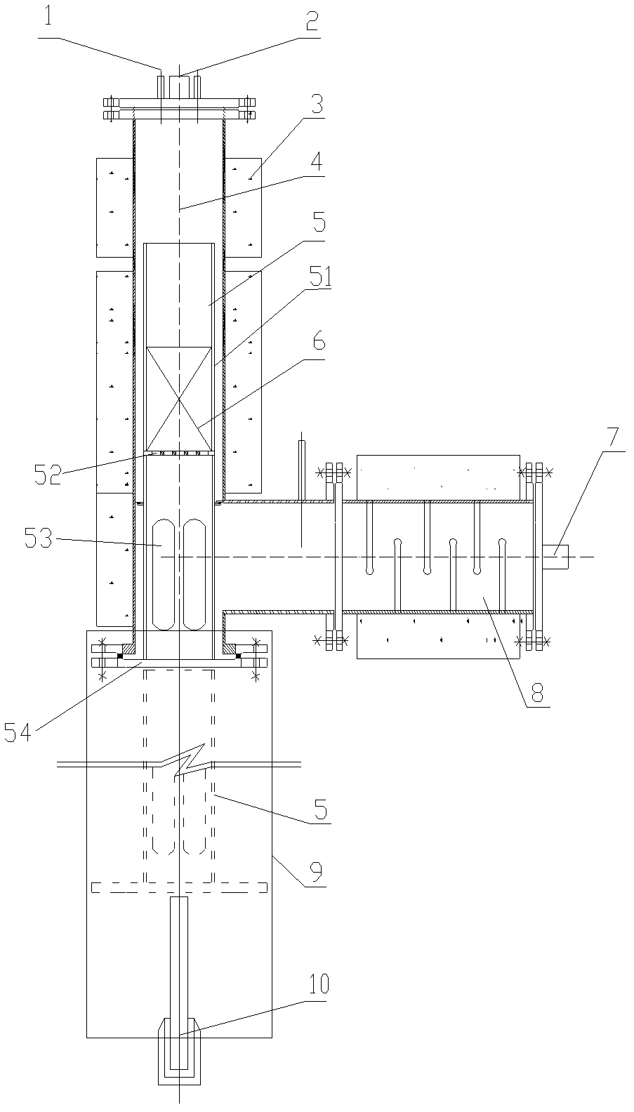
[0025] A certain amount of raw material is placed in the sagger 5, and the sagger 5 enters the reactor body 4 from the bottom (using a cracking furnace). Inert protective gas is introduced from the raw material gas inlet 9 to check the airtightness of the device. After the inspection is qualified, the heating electric furnace in the heating layer 3 is turned on to heat the reactor, and an inert gas is introduced for protection at the same time. When the temperature rises to the activation temperature of the catalyst, the reducing gas is introduced from the feed gas inlet 9 to ensure that the flow ratio of the inert gas and the reducing gas is constant. After the activation is complete, stop feeding the inert gas and reducing gas, and feed the raw gas CH from the raw gas inlet 9 4 , after being preheated by the gas preheater 8, the feed gas enters the carbon nanotube growth bed 6 for catalytic cracking reaction, CH 4 Catalytic cracking produces carbon nanotubes deposited on me...

Embodiment 2

[0028] A certain amount of catalyst is put into the sagger 5 of the reactor, and the sagger is installed into the reactor body 4 .

[0029] Set the program temperature controller so that the heating temperature of the cracking furnace is 650°C, the preheating temperature is 450°C, and the protective gas N 2 , catalyst reducing gas H 2 , feed gas CH 4 The flow ratio is about 12:2:1.

[0030] After reacting for 4h, stop feeding CH 4 , at N 2 Under the protection, the product is cooled in the first stage of the reactor, when the temperature of the reactor is reduced to 400 ° C, under N 2 The protection descends and moves the sagger 5 into the cooler 9 for cooling.

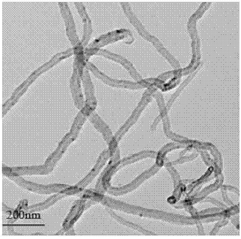
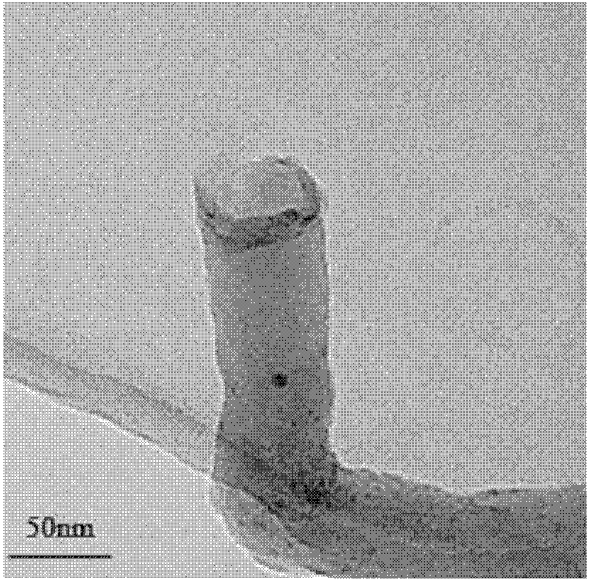
[0031] When the product temperature was cooled to room temperature, the product was taken out and weighed to obtain a carbon nanotube yield of 177.5g h -1 , by JEM-2100 (HR) transmission electron microscope (TEM) photos (see figure 2 with 3 ), it was observed that the outer diameter of carbon nanotubes was be...


PUM

PropertyMeasurementUnit
thicknessaaaaaaaaaa

Abstract

The invention discloses a reactor for semi-continuous production of a carbon nano tube, and relates to a reactor for producing a carbon nano tube. The reactor for semi-continuous production of the carbon nano tube has the advantages of simple structure, short operation cycle, low energy consumption, high space-time utilization rate of the equipment and the like, is convenient to operate and can enable a solid product to be quickly removed out of the reactor in high-temperature working condition. The reactor is provided with a reactor body, a saggar, a carbon nano tube bed layer, a gas preheater, a cooler and a saggar lifting air pump, wherein the top of the reactor body is provided with a thermocouple lead-out point and a tail gas outlet; the upper part of the reactor body is provided with a heating layer; the saggar is arranged in the reactor body; the carbon nano tube bed layer is arranged in the saggar; a raw gas inlet is arranged on one side of the gas preheater; a heating galvanic couple rod is arranged in the gas preheater; the gas preheater is arranged on one side of the lower part of the reactor body and connected with the reactor body; the cooler is arranged at the lower part of the reactor body and forms a vertical trapezoidal structure with the reactor body and the gas preheater; and the saggar lifting air pump is arranged in the cooler.

Description

technical field [0001] The invention relates to a reactor for producing carbon nanotubes, in particular to a reactor for semi-continuously producing carbon nanotubes. Background technique [0002] Carbon nanotubes are a one-dimensional quantum material with a unique structure, which is formed by curling graphitic carbon atomic layers. The diameter of the tube is generally several nanometers to tens of nanometers, the thickness of the tube wall is only a few nanometers, and the length can reach several microns. In 1991, Professor Iijima of NEC Corporation of Japan discovered multi-walled carbon nanotubes for the first time in the cathode deposits formed by the discharge of stone mill rods. There will be great application prospects in the field of science, which has attracted the great attention of many scientists, and has become one of the most popular research objects in nanotechnology. In recent years, countries such as the United States, Japan, Germany, and China have suc...

Claims


Application Information

Patent Timeline
Patent Type & Authority Applications(China)
IPC IPC(8): C01B31/02B82Y40/00C01B32/16
Inventor 汤培平朱丽林国栋张鸿斌刘宏宇金燕红李竞菲林康英
Owner XIAMEN UNIV
Why Eureka
Try Eureka