Molding device and molding method for long spiral extruding rock-entering cast-in-place pile

A forming device and a long screw technology, applied in drilling equipment and methods, sheet pile walls, earthwork drilling and mining, etc., can solve the problems of reducing pile end resistance, difficulty in ensuring pile body quality, and inability to effectively ensure grouting quality

Active Publication Date: 2012-07-04
SHAANXI ZHUANGXIN CONSTR ENG
View PDF10 Cites 31 Cited by
  • Summary
  • Abstract
  • Description
  • Claims
  • Application Information

AI Technical Summary

Problems solved by technology

However, in the actual construction process, the existing common long spiral hole-forming cast-in-situ piles have the following defects and deficiencies: first, the scope of application is limited, and it can only be applied in soil layers such as cohesive soil, silt, and filling soil. When sand pebble stratum or large-diameter pebble layer, then drilling is difficult or can't be drilled into; Thereby, the soil layer adaptability of existing long spiral hole-forming cast-in-situ pile is insufficient, and some areas cannot adopt; Second, existing long spiral hole forming The filling pile cannot enter the rock, so the pile end cannot be placed in the soil layer with high bearing capacity after the pile is formed, resulting in practical problems such as the low bearing capacity of the single pile; third, after the existing long spiral hole-forming cast-in-place pile is formed, the pile end After the soil is disturbed, it is easy to form virtual soil at the bottom of the hole, which reduces the resistance of the pile tip, thereby affectin...

Method used


Image

  • Molding device and molding method for long spiral extruding rock-entering cast-in-place pile
  • Molding device and molding method for long spiral extruding rock-entering cast-in-place pile
  • Molding device and molding method for long spiral extruding rock-entering cast-in-place pile

Examples


Embodiment Construction

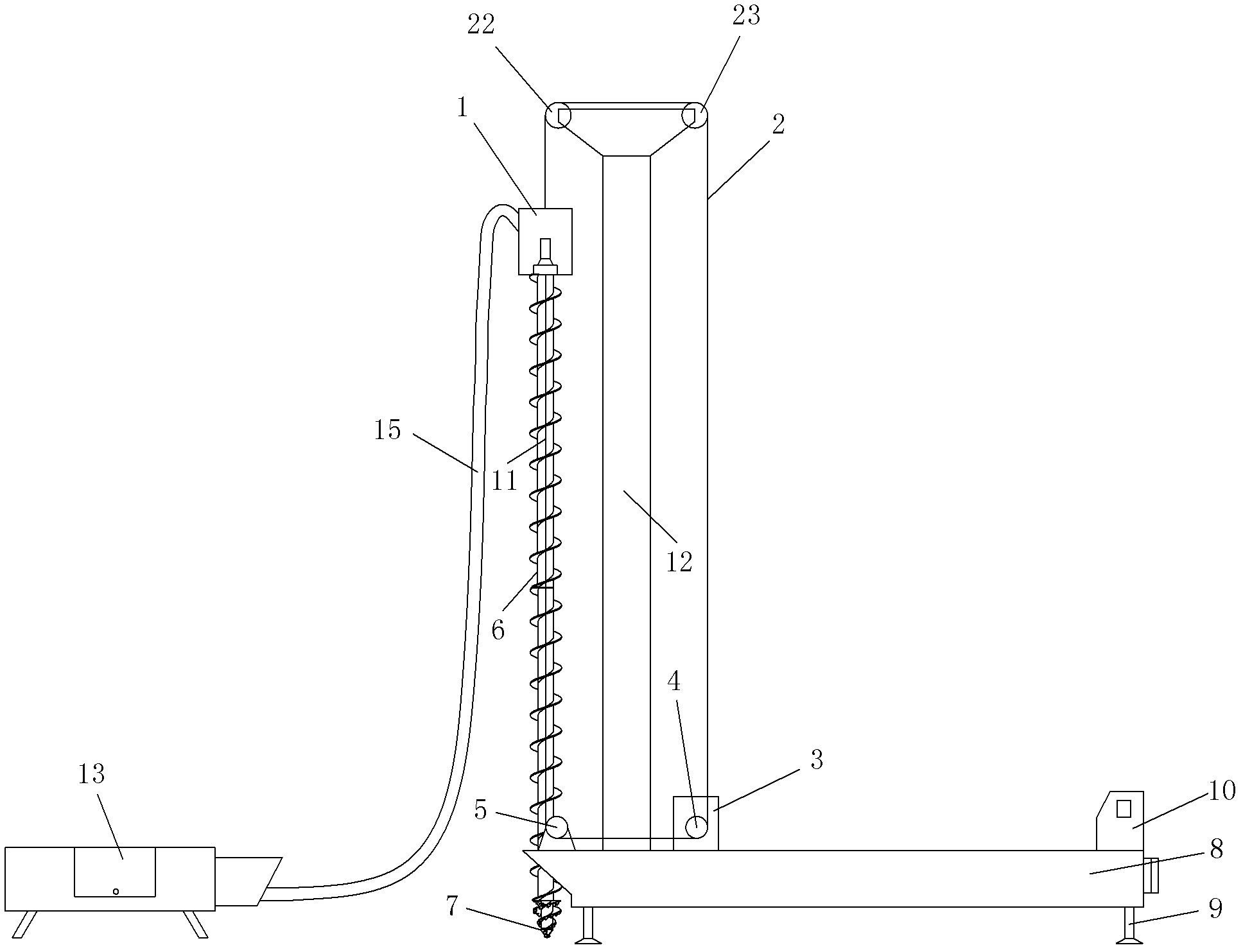
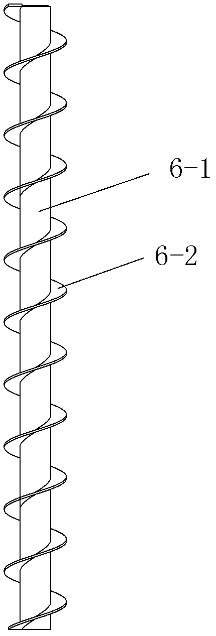
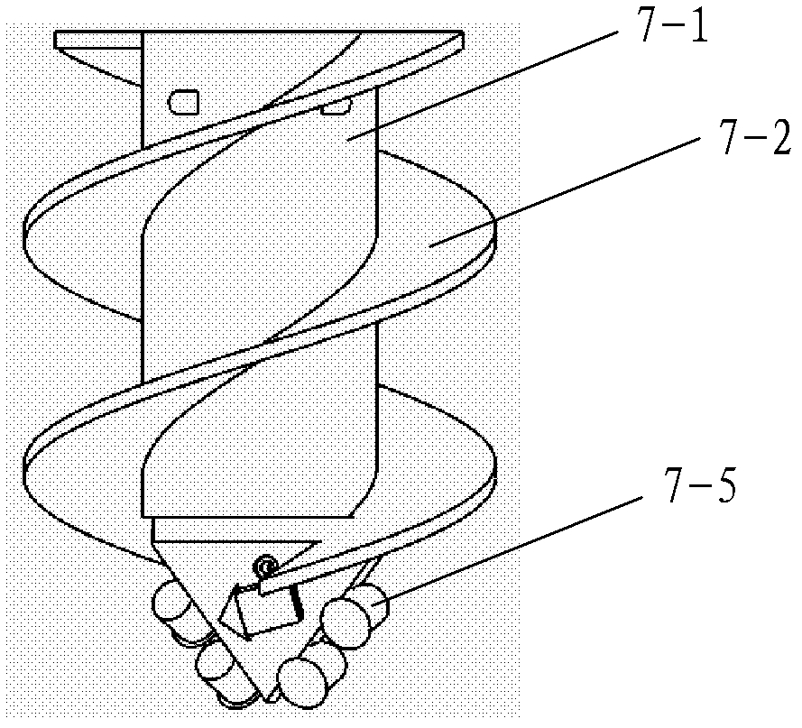
[0077] Such as figure 1 , Figure 9 A forming device for long spiral extruded cast-in-place piles shown includes drilling equipment formed by assembling a drill pipe 6 and a drill bit 7 coaxially installed at the bottom of the drill pipe 6. The lowering / lifting system for lifting the drilling equipment along the drilling direction after the drilling equipment is lowered and drilled in place, the electric rotary drive mechanism for driving the drilling equipment to rotate continuously, the lowering / lifting During the lifting process of the drill pipe 6, the system continuously injects grout into the formed borehole through the drill pipe 6 to form a grouting equipment for bored piles, and monitors the actual drilling depth of the drilling equipment in real time during the drilling process. The drilling depth / lifting height detection unit 4 that detects the actual lifting height of the drilling equipment in real time during the detection and lifting process, the drill rod torqu...


PUM


Abstract

The invention discloses a molding device and a molding method for a long spiral extruding rock-entering cast-in-place pile. The molding device comprises a drilling device formed by assembling a drill stem and a drill arranged at the bottom of the drill stem coaxially, a lowering/lifting system, an electric rotating driving mechanism for driving the drilling device to rotate continuously, a slip casting device for grouting casting slip into molded drill holes continuously to form bored piles when the lowering/lifting system lifts the drill stem, a drilling depth/lifting height detecting unit, a pumping flow detecting unit, a controller and a parameter input unit connected with the controller. The molding method includes: 1 setting initial parameters; 2 drilling; 3 further processing after drilling is in place; and 4 lifting the drill and slip-casting simultaneously. The molding device and the molding method are reasonable in design, easy to use and operate, high in automation, easy in molding process, easy in controlling of pile quality, wide in application range and capable of solving a plurality of problems in the existing molding devices and molding methods for the long spiral extruding rock-entering cast-in-place pile.

Description

technical field [0001] The invention belongs to the technical field of foundation construction, and in particular relates to a forming device and a forming method for a long spiral extruded cast-in-place pile. Background technique [0002] At present, in foundation projects such as construction, water conservancy, and highways, long spiral hole-forming cast-in-situ piles are widely used due to their advantages of high speed, low noise, no need for mud retaining walls, and low construction costs. However, in the actual construction process, the existing common long spiral hole-forming cast-in-situ piles have the following defects and deficiencies: first, the scope of application is limited, and it can only be applied in soil layers such as cohesive soil, silt, and filling soil. When sand pebble stratum or large-diameter pebble layer, then drilling is difficult or can't be drilled into; Thereby, the soil layer adaptability of existing long spiral hole-forming cast-in-situ pile...

Claims


Application Information

Patent Timeline
IPC IPC(8): E02D5/36E02D15/04E21B17/22E21B19/084E21B10/44E21B3/02E21B44/04
Inventor 庄金敖文庄春
Owner SHAANXI ZHUANGXIN CONSTR ENG
Why Eureka
Try Eureka