System and method for on-line detection of nitrogen in farmland soil

A soil nitrogen and detection system technology, applied in the field of agricultural sensing technology and instrumentation, can solve problems such as large time, financial and human resources, pollution, and chemical analysis methods cannot meet the requirements, and achieve the effect of accurate analysis

Active Publication Date: 2012-07-04
BEIJING RES CENT FOR INFORMATION TECH & AGRI
View PDF3 Cites 12 Cited by
  • Summary
  • Abstract
  • Description
  • Claims
  • Application Information

AI Technical Summary

Problems solved by technology

Traditional chemical analysis methods consume a lot of time, money and manpower. When soil analysis results need to be used to directly guide fertilization or field management, chemical analysis methods cannot meet the requirements in terms of real-time and practicality, and the distillation of waste liquid Improper handling of a large amount of high-concentration alkali can also cause environmental pollution

Method used


Image

  • System and method for on-line detection of nitrogen in farmland soil
  • System and method for on-line detection of nitrogen in farmland soil
  • System and method for on-line detection of nitrogen in farmland soil

Examples


Embodiment 1

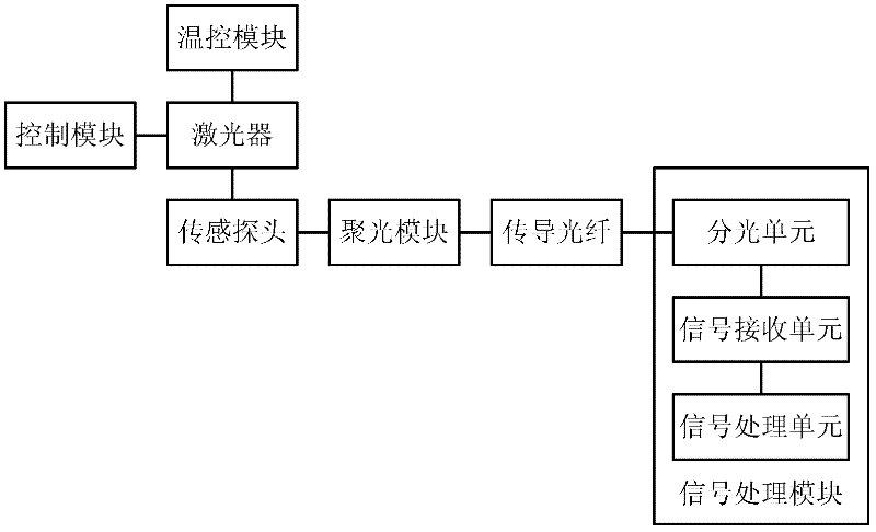
[0028] Such as figure 1 As shown, the farmland soil nitrogen online detection system according to an embodiment of the present invention includes: a laser, at least one set of sensing probes, a conductive optical fiber, and a signal processing module.

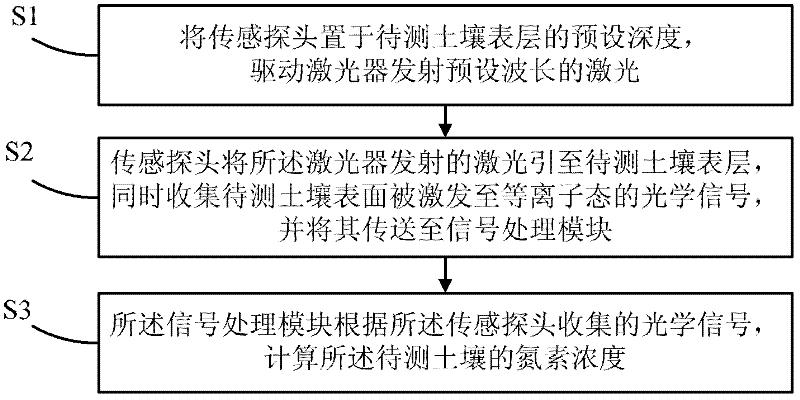
[0029] Wherein, the laser is used to emit laser light with a preset wavelength. When in use, place at least one set of sensing probes at a preset depth on the surface of the soil to be measured (when there are multiple sets of sensing probes, each set of sensing probes can be placed at different depths), for irradiating the light emitted by the laser to The surface layer of the soil to be measured is collected, and the optical signal that the soil surface to be measured is excited to a plasma state is collected. The conducting fiber is connected between the laser and the sensing probe, and between the sensing probe and the signal processing module, which guides the light emitted by the laser to the sensing probe, and transmits...

Embodiment 2

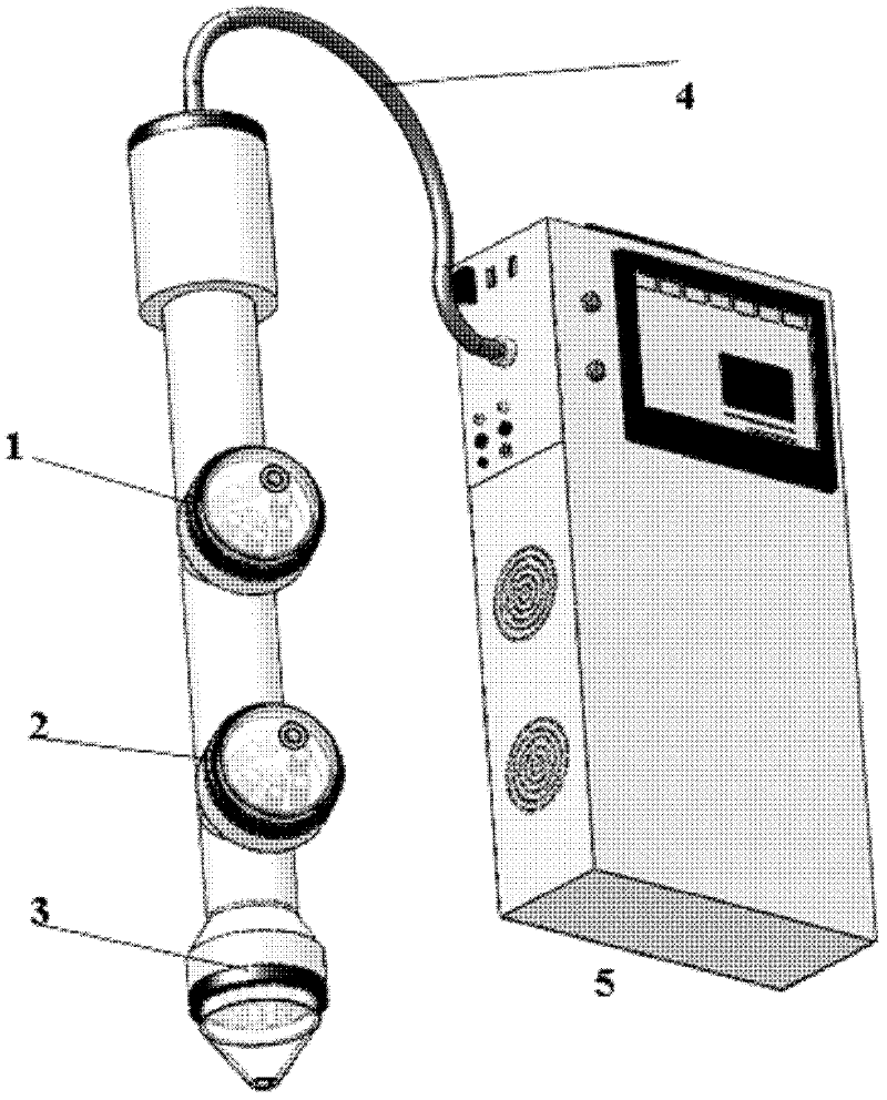
[0039] figure 2 The system shown in another embodiment of the present invention includes three sensing probes, respectively sensing probe 1, sensing probe 2, and sensing probe 3, and the three sets of sensing probes are respectively placed on the ground when in use. The following 20cm, 40cm, and 60cm are used for the measurement of soil nitrogen content in the three places. Each set of sensor probes has a built-in laser transmitter and 6 optical signal collection probes. Among them, the 6 optical signal collection probes are divided into two groups, one group receives the optical signal of 320nm-350nm, and the other group receives the optical signal of 490nm-520nm.

[0040] Optical signal transmission fiber 4 has 3 sets of optical fiber systems built in, one set is used to direct the laser signal to the sensor probe, one set is used to transmit the 320nm-350nm optical signal to the spectroscopic unit, and the other is used to transmit the 490nm-520nm optical signal to the S...


PUM

PropertyMeasurementUnit
wavelengthaaaaaaaaaa

Abstract

The invention discloses system and method for on-line detection of nitrogen in farmland soil and relates to the technical field of agricultural sensing techniques and devices. The system comprises a laser for emitting laser light of a preset wavelength; at least one sensing probe used for exposing the light from the laser to the surface of the to-be-detected soil and collecting optical signals which are emitted from the surface of the to-be-detected soil and excited to a plasma state; conducting optical fibers which are connected between the laser and the sensing probe and between the sensing probe and a signal processing module and used for guiding the light from the laser to the sensing probe and transmitting the optical signals collected by the sensing probe to the signal processing module; and a signal processing module used for calculating nitrogen concentration of the to-be-detected soil according to the optical signals collected by the sensing probe. The system and method are time-saving and labor-saving and have good real-time property and strong practicability.

Description

technical field [0001] The invention relates to the field of agricultural sensing technology and instrumentation technology, in particular to an on-line detection system and method for farmland soil nitrogen. Background technique [0002] Soil nitrogen in farmland is the main nutrient element that promotes crop growth, and on-site monitoring of nitrogen is of great significance. On the one hand, the real-time monitoring of nitrogen in the soil is an important basis for guiding scientific fertilization, so as to rationally use fertilizers, avoid excessive fertilization under the premise of ensuring the nutritional needs of crops, and enhance the quality and safety of agricultural products; on the other hand, soil nitrogen Real-time monitoring of nutrients is an important prerequisite for studying the law of soil nutrient migration and rationally planning agricultural operations. Soil science researchers urgently need to understand the real-time status of soil nitrogen conten...

Claims


Application Information

Patent Timeline
Patent Type & Authority Applications(China)
IPC IPC(8): G01N21/63
Inventor 赵春江郑文刚董大明赵贤德鲍锋申长军吴文彪
Owner BEIJING RES CENT FOR INFORMATION TECH & AGRI
Why Eureka
Try Eureka