Surface modification method of lithium iron phosphate cathode material

A technology of lithium iron phosphate and cathode material, applied in battery electrodes, electrical components, circuits, etc., can solve problems such as cumbersome surface coating technology

Active Publication Date: 2012-07-04
HUBEI WANRUN NEW ENERGY TECH DEV
View PDF2 Cites 22 Cited by
  • Summary
  • Abstract
  • Description
  • Claims
  • Application Information

AI Technical Summary

Problems solved by technology

[0015] In order to solve the cumbersome deficiency of the wet method surface coating technology of the existing lithium iron phosphate positive electrode material and improve the comprehensive performance of the lithium iron phosphate positive electrode ma

Method used


Image

  • Surface modification method of lithium iron phosphate cathode material
  • Surface modification method of lithium iron phosphate cathode material

Examples


Embodiment 1

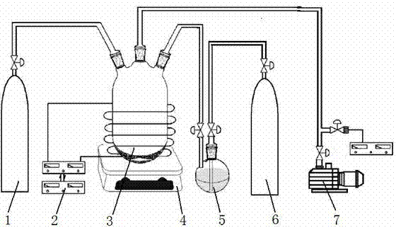
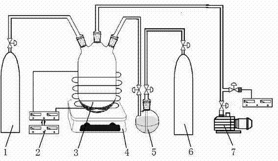
[0037] Weigh 5 grams of lithium iron phosphate cathode material powder into the plasma reactor 3, stir it in real time with a water bath magnetic stirrer 4, and control the temperature to 49-51°C. Pass the working gas N into the reactor 3 at a flow rate of 10 ml / min 2 , while passing carrier gas H into the organic monomer storage bottle 5 at a flow rate of 10 ml / min 2 , Liquid pyrrole is housed in the organic monomer storage bottle 5 . Pyrrole vapor and carrier gas H 2 into the plasma reactor 3 together. The reactor is continuously evacuated with a mechanical vacuum pump 7 to maintain a vacuum degree of 1-2 Pa in the reactor 3. Turn on the radio frequency power source 2, adjust the voltage to 30V, and the current to 20mA to generate plasma discharge in the reactor 3. The pyrrole monomer undergoes a polymerization reaction under the action of the plasma to generate a conductive polymer polypyrrole, which is coated on the surface of the lithium iron phosphate powder material...

Embodiment 2

[0040] Weighed 10 grams of lithium iron phosphate cathode material powder and put it into the plasma reactor 3, and stirred it in real time with the magnetic stirrer 4, and the temperature was normal temperature 25°C. Pass into the working gas Ar in the reactor 3 with the flow rate of 5 milliliters / minute, pass into the carrier gas He in the organic monomer storage bottle 5 with the flow rate of 5 milliliters / minute simultaneously, liquid state is housed in the organic monomer storage bottle 5 Thiophene. The thiophene vapor enters the plasma reactor 3 together with the carrier gas He. The reactor 3 is continuously evacuated with a mechanical vacuum pump 7 to maintain a vacuum degree of 0.1-0.2 Pa in the reactor 3. Turn on the radio frequency power source 2, adjust the voltage to 10V, and the current to 10mA to generate plasma discharge in the reactor 3. The thiophene monomer undergoes a polymerization reaction under the action of the plasma to generate a conductive polymer p...

Embodiment 3

[0043] Weigh 15 grams of lithium iron phosphate cathode material powder into the plasma reactor 2, stir it in real time with an oil bath magnetic stirrer 4, and control the temperature to 149-151°C. Pass the working gas N into the reactor 3 at a flow rate of 100 ml / min 2 , while passing carrier gas H into the organic monomer storage bottle 5 at a flow rate of 100 ml / min 2 , Liquid aniline is housed in the organic monomer storage bottle 5 . Aniline vapor and carrier gas H 2 into the plasma reactor 3 together. The reactor 3 is continuously evacuated with a mechanical vacuum pump 7 to maintain a vacuum degree of 10-20 Pa in the reactor 3. Turn on the radio frequency power source 2, adjust the voltage to 100V, and the current to 100mA to generate plasma discharge in the reactor. The aniline monomer undergoes a polymerization reaction under the action of the plasma to generate a conductive polymer polyaniline, which is coated on the surface of the lithium iron phosphate powder ...


PUM

PropertyMeasurementUnit
Reverse discharge specific capacityaaaaaaaaaa

Abstract

The invention relates to a surface modification method of a lithium iron phosphate cathode material. The surface modification method comprises conductive polymer cladding by plasma polymerization, surface fluorination, nitridation, vulcanization and so on. The method particularly comprises the steps of uniformly blending lithium iron phosphate powder with conductive polymer monomers, and placing the mixture into a discharge plasma reactor to clad the surface of lithium iron phosphate powder with the conductive polymer; or placing the lithium iron phosphate powder in the discharge plasma reactor, introducing working gas CF4, NH3, CS2 or H2S to generate F, N, S free groups by ionization, and subjecting lithium iron phosphate powder to surface fluorination, nitridation, vulcanization. The method provided by the invention has important meanings for improving the comprehensive performance of lithium iron phosphate cathode material, and particularly has significant effect in improving large-current charge-discharge capacity and low-temperature performance of the material. The modified material can be charged or discharged at 10C to 30C, and the discharge capacity at -20 DEG C is not less than 75% the normal temperature discharge capacity, so that the lithium iron phosphate cathode material is suitable for power cells.

Description

technical field [0001] The invention belongs to the technical field of energy material preparation, and in particular relates to a method for surface modification of lithium iron phosphate cathode materials, including plasma surface polymerization coating conductive polymers and plasma surface fluorination, nitriding, vulcanization and the like. Background technique [0002] Lithium iron phosphate cathode material has the advantages of high safety and long life, and is an ideal cathode material for lithium-ion power batteries. With the rapid development of new energy vehicles and other related industries, the market demand for power batteries has grown rapidly, and the demand for lithium iron phosphate cathode materials has also grown rapidly. [0003] In order to meet the requirements of power batteries, higher requirements are put forward for the high-current charge-discharge performance and low-temperature performance of lithium iron phosphate cathode materials. It is ge...

Claims


Application Information

Patent Timeline
IPC IPC(8): H01M4/62H01M4/58
CPCY02E60/12Y02E60/10
Inventor 应皆荣刘世琦
Owner HUBEI WANRUN NEW ENERGY TECH DEV
Why Eureka
Try Eureka