Coaxial resonant cavity mixed coupling method

A coaxial resonant cavity, hybrid coupling technology, applied in electrical components, circuits, waveguide devices, etc., can solve the problems of complex capacitive coupling structure, difficult to fine-tune the coupling strength, etc. Effect

Inactive Publication Date: 2012-07-04
XIDIAN UNIV
View PDF3 Cites 26 Cited by
  • Summary
  • Abstract
  • Description
  • Claims
  • Application Information

AI Technical Summary

Problems solved by technology

[0003] The purpose of the present invention is to overcome the problem that the capacitive coupling structure between existing coaxial resonators is complicated, and the coupling strength is not easy to fine-tune, and to provide a hybrid coupling method for coaxial resonators, which improves the frequency selection of filters and duplexers characteristic

Method used


Image

  • Coaxial resonant cavity mixed coupling method
  • Coaxial resonant cavity mixed coupling method
  • Coaxial resonant cavity mixed coupling method

Examples


Embodiment 1

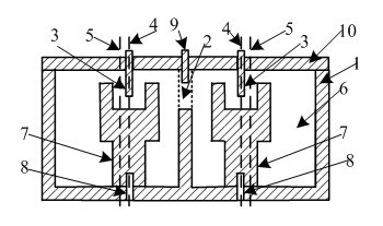
[0024] Such as figure 1 As shown, a coaxial resonant cavity hybrid coupling method includes a conductor shell 1, and two resonant cavities 6 are opened in the conductor shell 1, and the top of the conductor shell 1 is sealed by a conductor cover plate 10; each resonant cavity 6 includes a conductor Resonant rod 7, the upper end of the conductor resonant rod 7 has a cavity, the lower end is a rod body structure, the conductor resonant rod is cylindrical, the upper radius of the conductor resonant rod 7 is large, the lower radius is small, the cavity is at the upper end of the large radius, and the conductor resonant rod 7 The bottom end is fixed in the resonant cavity 6 by fastening screws 8, forming a vertical structure with the bottom surface of the resonant cavity 6, the conductor resonant rod 7 is a conductor, and contacts with the conductor shell 1 to form a short circuit; there is a tuning screw 3 on the conductor cover plate 10; the tuning screw 3. Adjust from top to bot...

Embodiment 2

[0027] The same coaxial resonant cavity hybrid coupling method also includes a conductor shell 1, and two resonant cavities 6 are opened in the conductor shell 1, and the top of the conductor shell 1 is sealed by a conductor cover plate 10; Including a conductor resonance rod 7, the upper end of the conductor resonance rod 7 has a cavity, the lower end is a rod body structure, the horizontal section of the conductor resonance rod is quadrilateral, the upper and lower radii of the conductor resonance rod 7 are the same, and the bottom end of the conductor resonance rod 7 is fixed by fastening screws 8 In the resonant cavity 6, it forms a vertical structure with the bottom surface of the resonant cavity 6, and the conductor resonant rod 7 is a conductor, which is in contact with the conductive shell 1 to form a short circuit; there is a tuning screw 3 on the conductor cover plate 10; the tuning screw 3 adjusts the extension guide from top to bottom In the cavity at the upper end ...


PUM


Abstract

The invention relates to the technical field of coaxial resonant cavity microwave filters and duplexers, in particular to a coaxial resonant cavity mixed coupling method. The method is characterized in that: a conductor shell is arranged; at least two resonant cavities are arranged in the conductor shell; the top of the conductor shell is sealed by a conductor cover plate; a conductor resonant rod is arranged in each resonant cavity, wherein the upper end of the conductor resonant rod is provided with a cavity and the lower end of the conductor resonant rod is in a rod body structure, the bottom end of the rod body structure is fixedly arranged in the resonant cavity through a fastening screw to form a vertical structure with the bottom surface of the resonant cavity, and the conductor resonant rod is a conductor and is contacted with the conductor shell to form short circuit; a tuning screw is arranged on the conductor cover plate; the tuning screw is adjusted from top to bottom and extends into the cavity body on the upper end of the conductor resonant rod; and the electromagnetic coupling intensity between the resonant cavities is finely tuned through a fine tuning screw. According to the coaxial resonant cavity mixed coupling method, the frequency selection characteristics of the filters and the duplexers are improved.

Description

technical field [0001] The invention relates to the technical fields of coaxial resonant cavity microwave filters and duplexers. In particular, it relates to a filter and a duplexer that realize electromagnetic hybrid coupling between resonant cavities, and to be exact, it is a coaxial resonant cavity hybrid coupling method. technical background [0002] Coaxial cavity microwave filter is an important part of the signal processing of microwave communication system and radar system. In order to obtain better frequency selection characteristics of the filter, the generalized Chebyshev filter is generally used at present. For the realization of the transmission zero of the generalized Chebyshev filter, the traditional design adopts the technology of cross-coupling. This technique often requires both capacitive and inductive coupling to be used together. The inductive coupling structure is relatively simple, while the capacitive coupling is usually realized with metal rods. ...

Claims


Application Information

Patent Timeline
Patent Type & Authority Applications(China)
IPC IPC(8): H01P1/20H01P1/205
Inventor 詹劲松陈晓龙王家礼
Owner XIDIAN UNIV
Why Eureka
Try Eureka