

Method and device for decomposing CO2 and H2O through thermo-chemistry circulation reaction system
A thermochemical cycle and reaction system technology, applied in chemical instruments and methods, separation methods, dispersed particle separation, etc., can solve the problems that are difficult to popularize and apply, the conversion rate and yield of catalytic hydrogenation reaction are not too high, and reach the reaction temperature Appropriate, easily scalable effects for industrial applications
- Summary
- Abstract
- Description
- Claims
- Application Information
AI Technical Summary
Problems solved by technology
Method used
Image

Examples
specific Embodiment 1
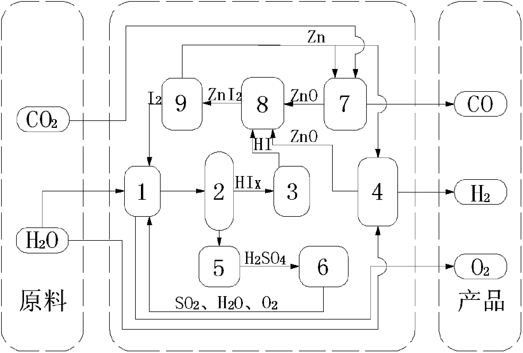
[0044] (1) 14molH 2 O, 1.5molI 2 and 1molSO 2 Send it into the Bunsen reaction device 1, stir the reaction solution at a constant speed by the motor device to ensure that it is evenly mixed, and an autonomous exothermic reaction occurs at 20 ° C and 1 atm to produce a watery HI phase (HI x ) and H 2 SO 4 Phase solution, in which the HI phase mainly contains hydrogen iodide solution and excess iodine, H 2 SO 4 Phase mainly contains H 2 SO 4 Solution, the chemical reaction formula of this reaction is as follows:
[0045] I 2 +SO 2 +2H 2 O→2HI+H 2 SO 4
[0046] (2) the two solutions in the Bunsen reaction unit 1 are separated in the liquid phase separation unit 2, H 2 SO 4 Phase in H 2 SO 4 After being concentrated in the concentration device 5, it enters the concentrated H 2 SO 4 In the catalytic decomposition device 6, it is first decomposed into SO at 350°C 3 and H 2 O, generated SO 3 Catalytic decomposition at 800°C to generate SO 2 and O 2 , the final...
specific Embodiment 2
[0056] (1) 15molH 2 O, 5molI 2 and 1molSO 2 Send it into the Bunsen reaction device 1, stir the reaction solution at a constant speed by the motor device to ensure that it is evenly mixed, and an autonomous exothermic reaction occurs at 70 ° C and 1.5 atm, producing a HI phase with more water (HI x ) and H 2 SO 4 Phase solution, in which the HI phase mainly contains hydrogen iodide solution and excess iodine, H 2 SO 4 Phase mainly contains H 2 SO 4 Solution, the chemical reaction formula of this reaction is as follows:
[0057] I 2 +SO 2 +2H 2 O→2HI+H 2 SO 4
[0058] (2) the two solutions in the Bunsen reaction unit 1 are separated in the liquid phase separation unit 2, H 2 SO 4 Phase in H 2 SO 4 After being concentrated in the concentration device 5, it enters the concentrated H 2 SO 4 In the catalytic decomposition device 6, it is first decomposed into SO at 350°C 3 and H 2 O, generated SO 3 Catalytic decomposition at 850°C to generate SO 2 and O 2 ,...
specific Embodiment 3
[0068] (1) 16molH 2 O, 9molI 2 and 1molSO 2 Send it into the Bunsen reaction device 1, stir the reaction solution at a constant speed by the motor device to ensure that it is evenly mixed, and an autonomous exothermic reaction occurs at 120 ° C and 2 atm to produce a watery HI phase (HI x ) and H 2 SO 4 Phase solution, in which the HI phase mainly contains hydrogen iodide solution and excess iodine, H 2 SO 4 Phase mainly contains H 2 SO 4 Solution, the chemical reaction formula of this reaction is as follows:
[0069] I 2 +SO 2 +2H 2 O→2HI+H 2 SO 4
[0070] (2) the two solutions in the Bunsen reaction unit 1 are separated in the liquid phase separation unit 2, H 2 SO 4 Phase in H 2 SO 4 After being concentrated in the concentration device 5, it enters the concentrated H 2 SO 4 In the catalytic decomposition device 6, it is first decomposed into SO at 350°C 3 and H 2 O, generated SO 3 Catalytic decomposition at 900°C to generate SO 2 and O 2 , the final ...
PUM
 Abstract
Description
Claims
Application Information