Fixed fluidized bed reactor for test

A fixed fluidized bed and reactor technology, applied in chemical instruments and methods, chemical/physical processes, etc., can solve problems such as thermal collapse of high-temperature catalyst particles, blockage of filters, shortening coexistence time, etc., to reduce the tendency of polymerization coking, Improve fluidization state, improve the effect of fluidization effect

Inactive Publication Date: 2012-07-11
洛阳康润石油化工科技开发有限公司
View PDF8 Cites 11 Cited by
  • Summary
  • Abstract
  • Description
  • Claims
  • Application Information

AI Technical Summary

Problems solved by technology

However, there are two common technical defects in these two patents: one is that the grid plate in the reactor is a flat plate structure with holes, and it is easy to accumulate on the upper surface of the unopened part of the grid plate during the fluidization process of the catalyst, causing some The catalyst cannot react with the raw material, which affects the accuracy of the test data and the cleanliness of the unloading agent; second, the outlet temperature of the reaction oil and gas is high, and the unsaturated components in it are easy to polymerize and coke on the outer surface of the filter, blocking the micropores of the filter Road, causing the reactor pressure to rise, directly affecting the accuracy and safety of the test
The fixed fluidized bed reactor described in CN201064712Y is an improved type of CN 2512495Y, and the difference is that the upper part of the latter's settling section is changed from a cylindrical shape to a circular truncated shape, so as to improve the linear velocity of the reaction oil and gas at the upper high-temperature part and shorten the middle of the reaction. The coexistence time of the product in the dilute phase section of the catalyst can effectively inhibit the polycondensation reaction between small molecular olefins, but the reactor ha

Method used


Image

  • Fixed fluidized bed reactor for test
  • Fixed fluidized bed reactor for test

Examples


Embodiment Construction

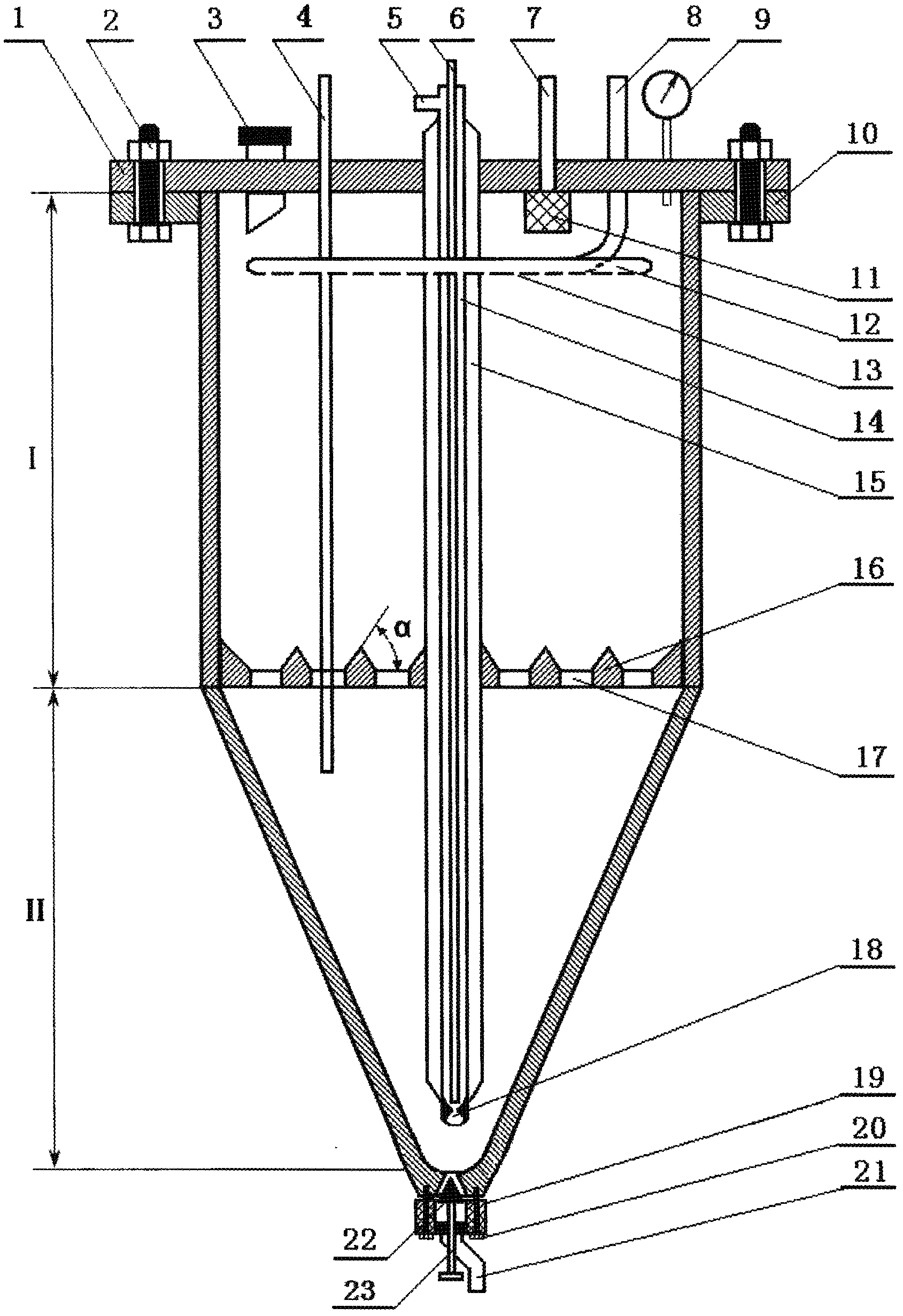
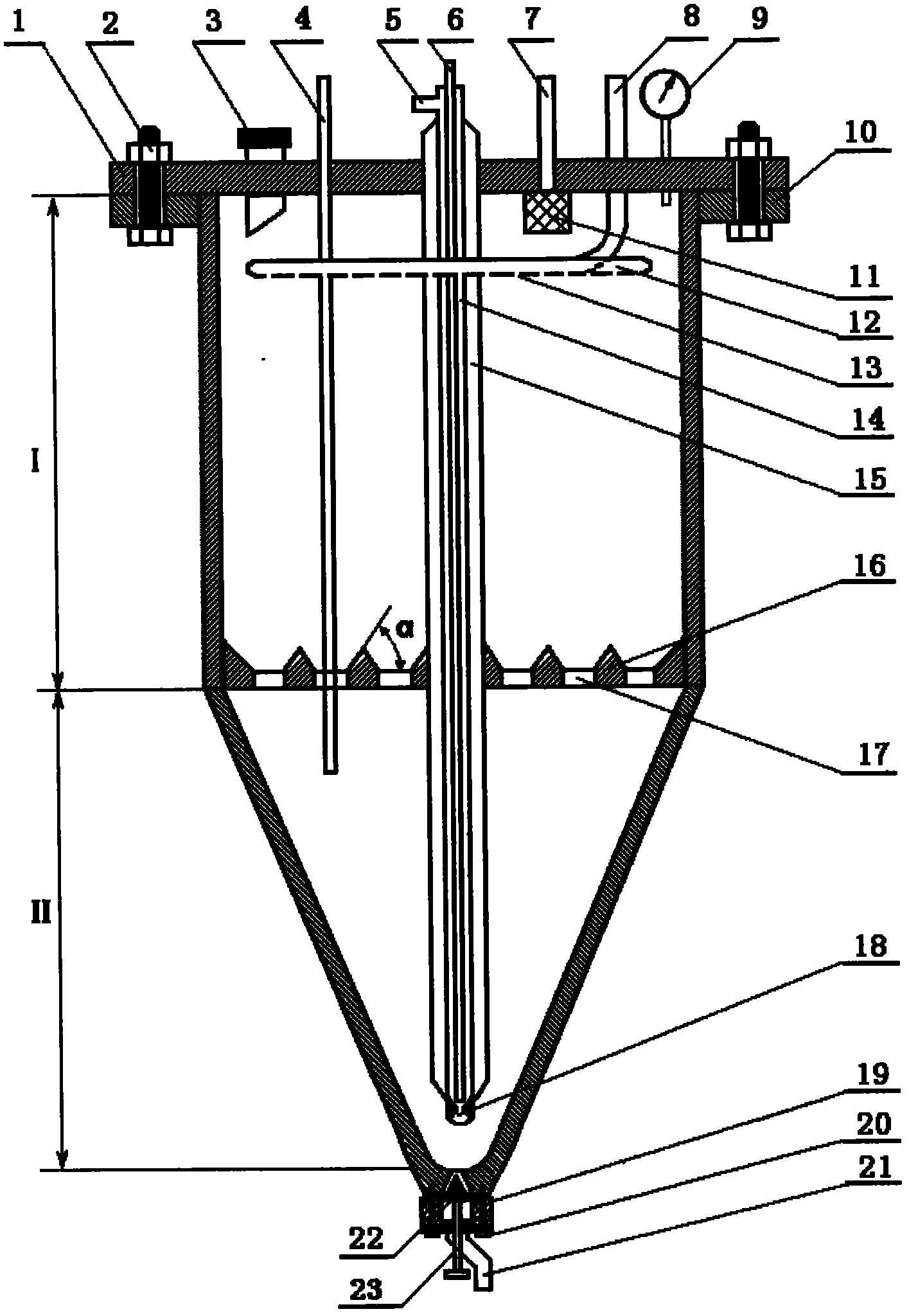
[0017] The present invention will be described in more detail below in conjunction with accompanying drawing, and its purpose is to illustrate content of the present invention better, but the protection scope of the present invention is not limited by the example of giving.

[0018] Such as figure 1As shown, a test fixed fluidized bed reactor consists of a cylindrical settling section I and an inverted conical reaction section II, the lower part of the cylindrical settling section I is the same diameter as the upper part of the inverted conical reaction section II and welded Fixed connection. The upper end of the cylindrical settling section I is sealed by a top cover flange 1, and the top cover flange 1 is fixedly connected with a lower flange 10 arranged on the outside of the top of the settling section I. On the top cover flange 1, there are catalyst feeding pipe 3, thermocouple casing 4, pressure gauge 9, and a concentric circle combination sleeve composed of raw material...


PUM


Abstract

A fixed fluidized bed reactor for tests comprises a cylindrical settling section [I] and an inverted conical reaction section [II]; the cylindrical settling section [I] and the inverted conical reaction section [II] are of a same diameter and are fixedly connected; an upper end of the cylindrical settling section [I] is sealed by a top cover flange [1]; the fixed fluidized bed reactor for tests also comprises a cooling medium inlet tube [8] and a cooling medium distributor [12] used for cooling materials in the reactor, a concentric combined casing pipe composed of a raw material oil inlet pipe [6], an atomized steam inlet pipe [14], and a heat insulation pipe [15], a grid plate [16] with a conical projection, and a conical plug valve [19] for discharging catalysts from the bottom. The reaction is applicable to both catalytic cracking and catalytic pyrolysis reactions, has the characteristics of a constant charging temperature and state, good raw material oil atomization, full agent-oil contact, complete agent discharging, a stable reaction pressure, and wide raw material application scope, can increase the security of the test process, and the accuracy and repeatability of test results.

Description

technical field [0001] The invention belongs to the technical field of petrochemical industry, and mainly relates to a fixed fluidized bed reactor used for experimental research. Background technique [0002] The catalytic cracking process is a heavy oil lightening process that converts heavy oil into light products such as gasoline, diesel and liquefied gas. It has the characteristics of strong raw material adaptability, high yield of target products, and good economic benefits. One of the core secondary processing techniques. The catalytic cracking process is a new technology for the production of olefins developed on the basis of the catalytic cracking process. It follows the mature process of catalytic cracking and uses high temperature, large ratio of fuel to oil, short residence time and special catalysts to produce gas products mainly including ethylene and propylene. , has become an important means to realize the integration of refining and chemical industry and imp...

Claims


Application Information

Patent Timeline
IPC IPC(8): B01J8/24
Inventor 李昕王晓丽苗伟
Owner 洛阳康润石油化工科技开发有限公司
Why Eureka
Try Eureka