Easily controlling hydraulic corner self-servo valve

A technology of self-servo and angle of rotation, applied in the field of servo valves, can solve problems such as unsatisfactory dynamic characteristics of the spool, unbalanced radial force of the spool, unsatisfactory servo dead zone, etc., and achieve small deformation of the valve port, resistance and hydraulic card Small tightening force and good dynamic characteristics

Active Publication Date: 2015-01-14
武汉科技大学资产经营有限公司
View PDF4 Cites 0 Cited by
  • Summary
  • Abstract
  • Description
  • Claims
  • Application Information

AI Technical Summary

Problems solved by technology

The radial force of the spool of the servo valve is balanced, and the resistance of the spool is reduced, but at the same time, there is also the problem that one end of the spool is easy to form a dead space. The spool generates a large axial force, the dynamic characteristics of the spool are not very ideal, and the servo dead zone has been improved but not ideal; It brings difficulties such as difficult preparation and processing of dark oil passages inside the valve body

Method used


Image

  • Easily controlling hydraulic corner self-servo valve
  • Easily controlling hydraulic corner self-servo valve
  • Easily controlling hydraulic corner self-servo valve

Examples


Embodiment 1

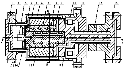
[0039] An easy -to -control hydraulic corner from the servo valve, such as figure 1 and figure 2 Show, the resignation rotor comes from the servo valve including fixed gear 5, cylinder body 6, valve body 7, valve cover 8, valve core 9, and leaves 15.

[0040] The left end of the cylinder 6 is equipped with a left end cover 1, a partition 16 in the cylinder 6 near the left end, and the inner wall of the tank 6 on the right side of the partition 16 is equipped with a fixed shield 5, a fixed shield 5 and a valve valveThe body 7 is a motion coordination. The fixed gear 5 and the valve body 7 are equipped with a block seal; the hollow cylindrical body 35 of the valve body 7 is fixed with leaves 15, leaf 15 and cylinder 6 are motion.Leaves 15 and the cylinder body 6 are equipped with a dense seal of the blades; the initial assembly position of the blade 15 and the fixed gear 5 is axisymmetric layout, and the leaf 15 and the fixed gear 5 are located on the lead vertical surface of the ax...

Embodiment 2

[0054] An easy -to -control hydraulic corner from the servo valve.Except for the following technical parameters, the remaining embodiments 1.

[0055] There are 2 valve ports evenly on the 4 -line lines of the valve core 9 cylindrical surface. Each valve port on each element line is connected through the oil channel, and the 4 plain lines are evenly distributed.The valve port corresponding to the other plain line is located at the same cross section;

[0056] The cylindrical surface of the valve cover 8 is evenly provided with 2 upper semi -cycloped oil rings 36 and 2 lower circular oil rings 37 along the axis.

Embodiment 3

[0058] An easy -to -control hydraulic corner from the servo valve.Except for the following technical parameters, the remaining embodiments 1.

[0059] There are 4 to 5 valve ports on the 4 -line lines of the valve core 9 cylindrical surface. Each valve port on each element line is connected through the oil channel, 4 plain lines are evenly distributed, and 4 on each prime line 4~ 5 valve ports as the valve port corresponding to the remaining vegetarian lines are located at the same cross section;

[0060] The cylindrical surface of the valve cover 8 is evenly provided with 4 to 5 upper semi -circular oil rings 36 and 4 ~ 5 lower semi -circular oil rings 37 along the axis.

[0061] The high -pressure oil imports of this specific embodiment entered the high -pressure oil channel 2 of the cylinder body 6 through its oil duct, and the exit of the high -voltage oil channel 2 in the cylinder body 6 into the high -pressure outer oil ring slot 31 of the valve body 7, and then through the ...


PUM


Abstract

The invention relates to an easily controlling hydraulic corner self-servo valve which is characterized in that a blade (15) is arranged on the outer wall of a hollow column body (35) of a valve body (7); the initial assembly position of the blade (15) is in axis symmetric arrangement with that of a fixed baffle block (5); a valve sleeve (8) is arranged in a the hollow column body (35), and a valve core (8) is arranged in a small hollow circle (34) of the valve body (7); a high pressure oil inlet P and a low pressure oil outlet T of a left end cover (1) are respectively communicated with high and low pressure outer oil annular slots (31 and 28) of the valve body (7) correspondingly through high and low pressure oil channels (2 and 17) of a cylinder body (6); high and low pressure inner oil annular slots (32 and 30) of the valve body (7) are correspondingly communicated with core body high and low pressure oil annular slots (39 and 40) of the valve core (9); and core body high and low pressure oil channels (38 and 41) enter a first working chamber and a and second working chamber correspondingly through upper and lower semi-circle oil annular slots (36 and 37) of the valve sleeve (8). According to the invention, the easily controlling hydraulic corner self-servo valve has the characteristics that the preparation is convenient, the radial force and the axial force subjected by the valve core are both balanced, the resistance of the valve core is low, the dynamic characteristics are good, and the servo blind area is small.

Description

Technical field [0001] The present invention is a technical field of the servo valve, and it involves a kind of easy -to -control hydraulic rotation corner from the servo valve. Background technique [0002] The hydraulic rotation is the core component of the hydraulic control system. It is widely used in the industry. It can convert the small power of the motor input into the high power of the hydraulic output in order to accurately turn the corner control of the device. [0003] At present, the hydraulic servo joints studied by Zhu Xinglong, a scholar of Yangzhou University in China for the first time using the hydraulic turning corner servo concept (Zhu Xinglong, Yan Jingping, Zhou Jiping, Miao Handong, alone.With manufacturing engineering, 2002,31 (6): 23-25.), (Zhu Xinglong, Zhou Jiping. A hydraulic servo joint stability and its steady-state error analysis. Control engineering, 2006,13 (1): 87-90.), The built -in and reduced hydraulic joint size of the hydraulic servo instit...

Claims


Application Information

Patent Timeline
Patent Type & Authority Patents(China)
IPC IPC(8): F15B13/02
Inventor 蒋林陈新元向贤宝赵杰曾良才赵慧金晓宏侯宇曾镛雷斌刘白雁许仁波
Owner 武汉科技大学资产经营有限公司
Why Eureka
Try Eureka