Gear-tooth block meshing switching device for linear reciprocating motion and rotational motion
A technology of reciprocating linear motion and conversion devices, which is applied in the direction of transmission devices, belts/chains/gears, mechanical equipment, etc., and can solve problems such as accelerated cylinder wall wear, piston inoperability, and increased lateral friction
- Summary
- Abstract
- Description
- Claims
- Application Information
AI Technical Summary
Problems solved by technology
Method used
Image
Examples
Embodiment 1
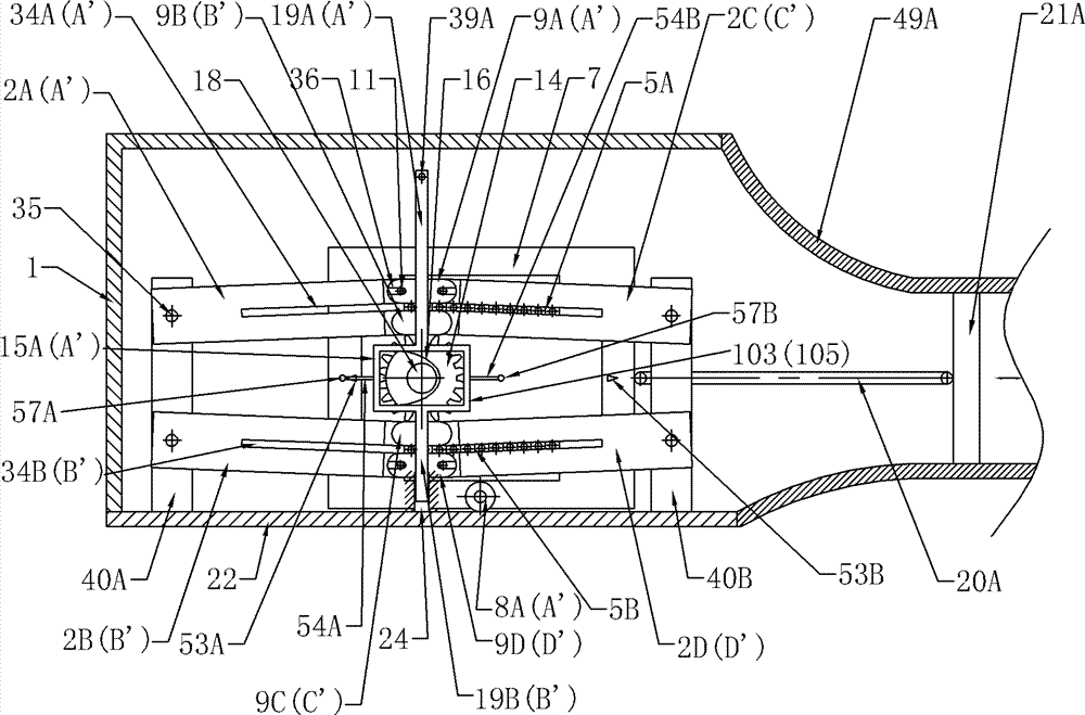
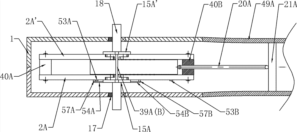
[0062] Such as Figure 1a , Figure 1b As shown, the reciprocating linear motion and rotary motion conversion device for gear-tooth block engagement of the present invention includes a housing 1, a transmission shaft 18, a gear block mechanism, a tooth block lifting mechanism, a first connecting rod 20A and a first piston 21A, and the gear Both the tooth block mechanism and the tooth block lifting mechanism are located in the housing 1 . Transmission shaft 18 is installed on the front and rear side walls of housing 1 through bearing 17 .
[0063] The gear block mechanism includes a gear 14, an upper tooth block arrangement 5A, a lower tooth block arrangement 5B, a drive frame mechanism 7, a left track plate set and a right track plate set.
[0064] The left track plate group includes the first track plate 2A, the second track plate 2A', the third track plate 2B and the fourth track plate 2B', and the right track plate set includes the fifth track plate 2C, the sixth track pla...
Embodiment 2
[0095] Embodiment 2 of the reciprocating linear motion and rotary motion conversion device provided by the present invention is different from Embodiment 1 in that:
[0096] Such as Figure 6a , 6b , 7a, 7b, on the top surface of each tooth block 6 of the upper tooth block arrangement 5A and the first and second end tooth blocks 6A, 6B, an open tooth block groove 37 is opened along the middle line, and on the lower tooth block The bottom surface of each tooth block 6 of the block arrangement 5B and the third and fourth end tooth blocks 6C, 6D defines an open tooth block groove 37 along the midline, and the depth of the tooth block groove 37 is greater than twice the gear tooth height. An upper support rod 38A is installed in the tooth block groove 37 of the upper tooth block arrangement 5A, and a lower support rod 38B is installed in the tooth block groove 37 of the lower tooth block arrangement 5B. The upper support rod 38A and the lower support rod 38B can be positioned at ...
Embodiment 3
[0100] Such as Figure 8a , Figure 8b As shown, the difference between this embodiment and Embodiment 1 is that: the lifting plate 41 is used instead of the cam to drive the first lifting frame 15A, and the limiting triangular block, the limiting rod and other parts are not provided in this embodiment. bit device. combine Figure 10a , Figure 10b As shown, the lifting pin 44 is set on the rear side of the first lifting rod 19A of the first lifting frame 15A, and the lifting plate 41 is fixedly installed on the upper frame 56A of the drive frame mechanism 7, and the front side of the lifting plate 41 is opened. Oval lift groove 42, lift groove 42 comprises two horizontal straight grooves and arc grooves connecting the two ends of the two horizontal straight grooves, the distance between the centerlines of the horizontal straight grooves is equal to 2 times of the tooth height of gear 14, lift groove 42 The width is equal to the diameter of the lift pin 44, and the lift pi...
PUM
 Abstract
Description
Claims
Application Information
 - R&D
- Intellectual Property
- Life Sciences
- Materials
- Tech Scout
- Unparalleled Data Quality
- Higher Quality Content
- 60% Fewer Hallucinations
Browse by: Latest US Patents, China's latest patents, Technical Efficacy Thesaurus, Application Domain, Technology Topic, Popular Technical Reports.
© 2025 PatSnap. All rights reserved.Legal|Privacy policy|Modern Slavery Act Transparency Statement|Sitemap|About US| Contact US: help@patsnap.com


